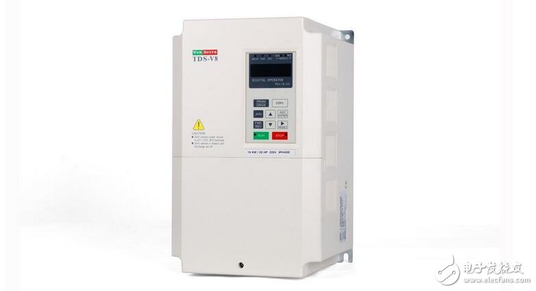
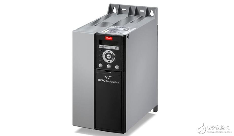
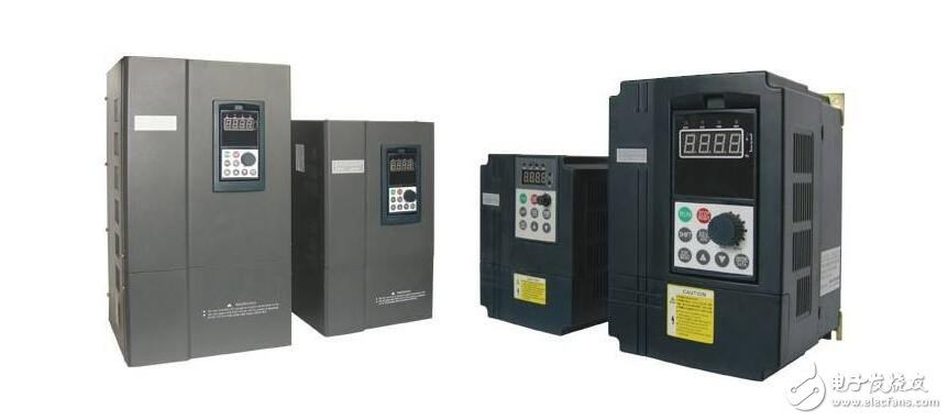
Variable-frequency drive (VFD) is a power control device that controls the AC motor by changing the working frequency of the motor by applying variable frequency technology and microelectronic technology. The frequency converter is mainly composed of rectification (AC to DC), filtering, inverter (DC to AC), braking unit, drive unit, and detection unit micro processing unit. The inverter adjusts the voltage and frequency of the output power supply by the internal IGBT breaking, and supplies the required power supply voltage according to the actual needs of the motor, thereby achieving the purpose of energy saving and speed regulation. In addition, the frequency converter has many protection functions. Such as overcurrent, overvoltage, overload protection and so on. With the continuous improvement of industrial automation, inverters have also been widely used.
Frequency conversion speed regulation technology is an important development direction of modern electric drive technology, and as the core of variable frequency speed control system - the performance of frequency converter is becoming more and more the decisive factor of the speed control performance, except for the "innate" manufacturing process of the inverter itself. In addition to the conditions, it is also very important to control the inverter.

1, the basic structure of the inverter
The frequency converter is a device that converts a commercial power supply (50 Hz or 60 Hz) into an AC power supply of various frequencies to realize variable speed operation of the motor, wherein the control circuit completes control of the main circuit, and the rectifier circuit converts the alternating current into direct current, and the middle of the direct current The circuit smoothes the output of the rectifier circuit, and the inverter circuit re-inverts the DC power into AC power. For a frequency converter such as a vector control inverter that requires a large amount of calculations, sometimes a CPU for torque calculation and some corresponding circuits are required.

2, the working principle of the inverter:
The frequency converter is a device that converts alternating current with constant voltage and frequency into alternating current with variable voltage or frequency, and has a wide range of applications in actual production.
The working principle of the inverter is to control the main circuit through the control circuit. The rectifier in the main circuit converts the alternating current into direct current, the DC intermediate circuit smoothes the direct current, and the inverter finally converts the direct current into the alternating current of the desired frequency and voltage. Some inverters also add components such as CPU to the circuit to perform necessary torque calculations.
The main circuit is a power conversion part that supplies a voltage-regulating and frequency-modulated power supply to the asynchronous motor. The main circuit of the frequency converter can be roughly divided into two types: the voltage type is a frequency converter that converts the direct current of the voltage source into an alternating current, and the filtering of the direct current circuit is a capacitor. . The current type is a frequency converter that converts the direct current of the current source into an alternating current, and the direct current loop filtering is an inductance. It consists of three parts, which converts the power frequency power supply into a "rectifier" of DC power, and absorbs the "pulse-wave loop" generated by the voltage ripple generated by the converter and the inverter.
The frequency converter is an electrical equipment that converts the power frequency power into any frequency and any voltage AC power. The use of the frequency converter is mainly to adjust the power of the motor and realize the variable speed operation of the motor. The composition of the frequency converter mainly includes two parts of the control circuit and the main circuit, wherein the main circuit also includes components such as a rectifier and an inverter.
Common control methods in the inverter:The non-intelligent control methods used in the AC drive include V/f coordinated control, slip frequency control, vector control, and direct torque control.
(1) V/f control
V/f control is to obtain the ideal torque-speed characteristic. Based on the idea of ​​changing the power frequency to adjust the speed while ensuring the magnetic flux of the motor is unchanged, the general-purpose inverter basically adopts this. Kind of control. The V/f control inverter structure is very simple, but the inverter adopts open-loop control mode, which can not achieve high control performance. Moreover, at low frequencies, torque compensation must be performed to change the low-frequency torque characteristics.
(2) Slip frequency control
Slip frequency control is a control method that directly controls the torque. It is based on the V/f control, and the frequency of the power supply corresponding to the actual speed of the asynchronous motor is known, and the inverter is adjusted according to the desired torque. By outputting the frequency, the motor can have a corresponding output torque. This kind of control method requires the installation of a speed sensor in the control system, and sometimes a current feedback to control the frequency and current. Therefore, this is a closed-loop control mode, which can make the frequency converter have good stability and Rapid acceleration and deceleration and load changes have good response characteristics.
(3) Vector control
Vector control is to control the magnitude and phase of the stator current of the motor through the vector coordinate circuit to control the excitation current and torque current of the motor in the d, q, 0 coordinate system, respectively, to achieve the purpose of controlling the motor torque. By controlling the sequence and time of each vector and the action time of the zero vector, various PWM waves can be formed to achieve various control purposes. For example, a PWM wave with the fewest number of switching times is formed to reduce switching loss. At present, the vector control methods actually applied in the frequency converter mainly include two kinds of vector control methods based on slip frequency control and vector control methods without speed sensor.
The vector control method based on the slip frequency is consistent with the steady-state characteristics of the slip frequency control method, but the vector control based on the slip frequency also controls the phase of the motor stator current through coordinate transformation to satisfy certain conditions. To eliminate fluctuations in the torque current transition process. Therefore, the vector control method based on the slip frequency can be greatly improved in output characteristics compared to the slip frequency control method. However, this control method is a closed-loop control method, and a speed sensor needs to be mounted on the motor, so the application range is limited.
The speed sensorless vector control controls the excitation current and the torque current by coordinate transformation processing respectively, and then controls the excitation current and the torque current by controlling the voltage and current on the stator winding of the motor to identify the excitation current and the torque current. This control mode has a wide speed range, large starting torque, reliable operation and convenient operation, but the calculation is complicated, and generally requires a special processor for calculation. Therefore, the real-time performance is not too ideal, and the control precision is affected by the calculation accuracy. .

(4) Direct torque control
Direct torque control uses the concept of space vector coordinates, analyzes the mathematical model of the AC motor in the stator coordinate system, controls the flux linkage and torque of the motor, and detects the stator flux by detecting the stator resistance, thus eliminating the need for Complex transformation calculations such as vector control, the system is intuitive and concise, and the calculation speed and accuracy are improved compared with the vector control method. Even in the open loop state, 100% of rated torque can be output.
(5) Optimal control
The application of the optimal control in practice varies according to the requirements, and the individual parameters can be optimized for a certain control requirement according to the theory of optimal control. For example, in the control application of high-voltage inverters, two strategies of time segmentation control and phase shift control are successfully adopted to achieve the optimal voltage waveform under certain conditions.
(6) Other non-intelligent control methods
In practical applications, some non-intelligent control methods are implemented in the control of the frequency converter, such as adaptive control, sliding mode variable structure control, difference frequency control, circulating current control, frequency control, and the like.
High Quality Tablet Ram 4GB/8GB/16GB SODIMM UDIMM DDR4 8gb Laptop 2400mhz Ram
Model
DDR4 SODIMM
Brand
Semsotai /OEM /ODM /OBM
ECC
Non-ECC
Capacity
4GB/8GB/16GB
Chipsets
Samsung /SK Hynix/Mircon/Spec tek
Frequency
2133MHz/2400MHz/2666MHz/3200MHz
Speed
PC4-17000/PC4-19200/PC4-21300/PC4-25600
Componets Configuration
(256m/512m/1G) x8/x16
Memory CAS Lantency
CL15/CL17/CL19/CL21/CL22
Supply Voltage
1.2V
Pin Count
260PIN
PCB layer
8 /10 layer high speed PCB
Certificate
CE/FCC/ROHS
Operation temperature
0C-95C
Compability
100% Work with all motherboard
Ddr4 Laptop Memory,Ddr4 Rgb Ram,Ddr3 Ram 8Gb Pc 1600,Game Ddr3 8Gb
MICROBITS TECHNOLOGY LIMITED , https://www.hkmicrobits.com