Overview:
With the development of new energy technologies, microgrid technology has been more and more widely used. The inverter source is the main component of the microgrid. The stability of the inverter source directly affects the power quality of the microgrid. The main determinant of the quality and dynamic performance of the PWM inverter output waveform is the use of control and implementation methods.
Based on Matlab software platform, the inverter source designed by double loop control strategy is modeled and simulated by Matlab-Simulink-SimPowerSystems toolbox, which verifies the feasibility and effectiveness of the design scheme.
0 Introduction With the development of renewable energy such as solar energy and wind energy, distributed power generation has become a hotspot of research in various countries due to its advantages of less environmental pollution, high energy comprehensive utilization and reliable power supply. Mature countries and regions to apply them widely in the microgrid. As an effective power supply source, inverter power has become an important part of microgrid, and has been widely used in the research and implementation of microgrid.
The PWM-based isolated inverter power supply designed in this paper adopts voltage outer loop and current inner loop double loop control strategy. Both voltage outer loop and current inner loop adopt PI control mode. The Matlab software was used to establish the experimental model for simulation. The rationality of the control system design scheme and the application effect of the double loop control strategy were verified by simulation. The simulation results proved the rationality and effectiveness of the system design scheme.
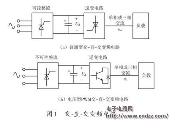
1 PWM inverter circuit structure and working principle In the AC-DC-AC inverter, the DC circuit is usually required to adopt the thyristor rectifier circuit, as shown in Figure 1(a). The magnitude of the voltage Uo of the inverter output can be controlled by changing the size of Ud. The frequency of the output voltage Uo can be changed by controlling the frequency of the inverter trigger circuit. However, this type of frequency conversion circuit has drawbacks: if the output AC voltage is a rectangular wave containing more harmonics, this is disadvantageous for the load or the AC grid; if the output power is adjusted by the phase control method, The input power factor is reduced, and the large capacitance is present in the intermediate DC ring, so that the inertia is large when the input power is adjusted, and the system response is slow.
In order to solve the above drawbacks, an inverter circuit as shown in Fig. 1(b) can be employed. This kind of circuit is usually called PWM (Pulse Width Modulation) type frequency conversion circuit. Its basic working principle is to control the on/off of the switching device in the inverter circuit regularly, so that the output end can be equal in width. Pulse trains, and use these pulse trains instead of sine waves. Modulating the pulse widths of the pulse train according to the required rules can change the output voltage of the circuit and change the frequency of the output voltage.

(Please read the PDF for details)
Programmable DC Power Supplies
The CSP series Programmable DC Power Supply is upgraded and developed on the basis of iDealTek-Electronics' mature IGBT high frequency switching power topology and all-digital signal control loop. Featured with high precision, low ripple and fast response speed.
The Programmable DC Power Supply is different from the traditional DC power supply that can only control the output voltage and current values. The programmable DC Power Supplies can realize the programming of multiple parameters through adding the microprocessor unit with built-in control program, such as parameters like operating time, output rise time, protection response time, OVP and OCP etc. All can be set and programmed.
At the same time, the microprocessor unit also adds more functions to the power monitoring system, which can realize the query of the historical data of the test results, making the programmable DC power supply the best choice for laboratory test, production line manufacturing test, photovoltaic plate aging test and various cutting-edge applications with Programmable DC power supplies.
This series of Programmable Power Supplies have a total of 4 standard rated power levels, ranging from 1KW Desktop Programmable Laboratory power supplies to 3KW / 6KW / 10KW Rack-mounted Programmable DC power supplies. The maximum output voltage ranges from 600V to 1000V under different rated powers.
Beautiful appearance design with small and compact size, the whole series power supplies adopt silicone buttons, stepless knobs and LCD display on control panel layout. The output voltage, current, start / stop time, output rising rate, OVP, OCP and other parameter setting programming and reading of the Programmable Power Supplies can be easily and quickly completed through the front panel man-machine interface, up to 5 digits of high-precision programming and monitoring levels make the measurement results of the programmable DC power supply accurate and reliable, almost no need to use external power meters.
At the same time, the whole series of programmable DC power supplies are equipped with RS485 interface as standard, following the MODBUS-RTU international protocol, which can realize remote control programming, test results save and uploading to the master unit and status monitoring of the power supply.
Programmable Power Supplies, DC Programmable Power Supplies, Programmable AC - DC Power Supplies, Programmable AC DC Power Supplies, Programmable Laboratory Power Supplies
Yangzhou IdealTek Electronics Co., Ltd. , https://www.idealtekpower.com