Narrowband Frequency Modulation Principle and SystemView Simulation
Common analog modulations include angle modulation (FM / PM) and amplitude modulation (AM / DSB). Unlike amplitude modulation, angle modulation is a non-linear shift of the original modulated signal spectrum and produces new spectral components, so it is also called Non-linear modulation. FM (Frequency Modulation) is widely used in practical communications, such as high-fidelity music broadcasting, TV sound signal transmission, cellular phones, and satellite communications. Compared with amplitude modulation, FM can obtain higher anti-noise performance. This article discusses the modulation and demodulation principle of Narrow-Band FM (Narrow-Band FM), which is a special case in FM, and uses the communication simulation software SystemView for simulation analysis. The purpose is to show readers the complete use of EDA (Electronic Design Automatlon Electronic Design Automation) technical analysis of ideas and processes to solve communication problems.
1 Basic principles of narrowband FM
1.1 Modulation principle
The general expression of the angle modulation signal is: ![]()
The so-called frequency modulation (FM) refers to the instantaneous frequency offset △ ω changes in proportion to the modulation signal f (t), namely: 

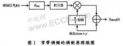
At this point, a general expression for narrowband frequency modulation is obtained. Using equation (7) as a mathematical model, the principle block diagram of narrow-band frequency modulation can be established directly, as shown in Figure 1. 
1.2 Demodulation principle
It can be seen from the above derivation that narrow-band frequency modulation can be realized by a multiplier, so it is necessary to use the coherent demodulation method to restore the original modulated signal. As shown in Figure 2, the NBFM signal is first filtered by a band-pass filter (BP) at the receiving end The additive noise of the channel outside the frequency band is then multiplied by the carrier (-sinωct), and the high-frequency component filtered by a low-pass filter is removed, and finally the integral outside f (t) is removed by the differentiator, at the output Restore the original modulated signal f (t).

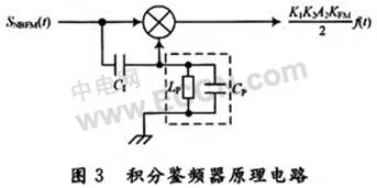
Another type of FM demodulator is the so-called integral discriminator, as shown in Figure 3. This type of FM demodulator has been used in many monolithic FM radio and receiver chips. 
In Fig. 3, the frequency-modulated signal is divided into two paths, one path is directly connected to the multiplier, and the other path generates a quadrature signal through a coupling capacitor and a LC parallel resonant circuit as another input of the multiplier. All phase shifts consist of the phase shift produced by the coupling capacitor and the additional phase shift produced by the resonant circuit.
The simple principle is as follows:
In order to simplify the problem, the input NBFM signal is simply expressed in the form of a general angle modulation signal: ![]()
Then another signal generated by the above phase shift network is: ![]()
In the type: The coefficient C1, C2 is determined by the circuit parameter. The output of the two signals after passing through the multiplier is: 
Among them, the sum term in the latter frequency component can be filtered by LP (low pass filter), so the output can be simplified as: 
Where: f (t) is the modulation signal. In addition, to obtain the approximate result of equation (10), the coefficient C2 is also required to be sufficiently small.
In particular, there is no phase shift network formed by coupling capacitors and resonant circuits in actual computer simulations, and only other methods can be used to achieve phase shift. One method is to use a Hilbert transform filter to achieve, because the Hilbert filter will cause the signal within the entire pass to produce a 90 ° phase shift; the other method is through a simple stiffening circuit A delay equivalent to 1/4 cycle of the carrier is generated, resulting in a 90 ° phase shift at the center frequency of the carrier. Of course, this is an ideal approximation, which dilutes some of the problems that will occur in the actual phase-shift circuit, but this does not affect the analysis and judgment of the entire modulation and demodulation process.
2 SystemView simulation process
2.1 Establish a simulation model
Based on the above discussion and analysis, referring to the modulation and demodulation principle block diagram of the narrowband FM signal, a complete simulation model is established in the communication simulation software Systemview as shown in FIG. 4. 
Description: The narrow-band FM modulation module established with reference to Figure 1 is also called indirect FM modulation; the demodulation module is established with reference to Figures 2 and 3, which consists of two methods: coherent demodulation and integral discriminator demodulation. There are two types of delay method and Hilbert method in completing the 90 ° phase shift.
In actual simulation, the simulation parameters can be flexibly changed according to the actual situation, in order to achieve a better simulation effect. It should be noted that the setting of the delay Delay: Assuming that the carrier frequency is 500 Hz, set the sampling frequency of the simulation system to 2 000 Hz, which is exactly 4 times the carrier, that is, the system sampling period (1/2000 = 500 μs) It is 1/4 of the carrier cycle. You can choose to delay just one system sampling period of 500μs, which is delayed by 1/4 of the carrier period, so as to achieve the purpose of phase shift by 90 °.
2.2 Analysis of simulation results
Run the simulation and export the resulting waveform directly from the SystemView analysis window after completion.
Figure 5 is the spectrum diagram of the NBFM signal calculated by the SystemView receiving calculator (only one side is taken after zooming), the center is the carrier frequency component of 500 Hz, and the positive upper side frequency (small bumps on both sides of the figure) is located at 505 At Hz, the negative lower side frequency is at 495 Hz, which is consistent with the previous estimate of the NBFM signal spectrum. It seems that NBFM is very similar to the familiar AM spectrum. As a comparison, the spectrum diagram of a conventional AM amplitude modulation signal is shown in Figure 6. Comparing the upper and lower sidebands, it is found that the lower sideband of NBFM is inverse to AM. In order to further distinguish them, you can draw a vector addition diagram, as shown in Figure 7. 
As can be seen from FIG. 7, in NBFM, since the lower side frequency is negative, their combined vectors are orthogonally added to the carrier, so that there is a phase change Δφ of NBFM. When equation (5) is satisfied, Δφ is very small, and the amplitude change caused by it can be ignored. This is the essence of NBFM, which belongs to angle modulation and is distinguished from AM. Because in AM, the composite vector of the upper and lower sidebands is in phase with the carrier, and there is no phase change.
The two demodulation methods of NBFM are compared based on the simulation results.
In order to facilitate intuitive comparison, the signals demodulated by the two methods are drawn on the same picture, as shown in Figure 8. Obviously, the effect of coherent demodulation is better, and the signal distortion is less. From the amplitude of the demodulated signal, the coherent demodulated signal amplitude is about 50 times that of the discriminator (the initial amplitude of the modulated signal is set to 1). This is related to the process of NBFM signal generation. Because narrowband frequency modulation is implemented by a multiplier, coherent demodulation is the most direct and the least error method (this is similar to AM amplitude modulation). However, the integral discriminator method suitable for demodulation of ordinary FM signals is not effective in simulation. Whether it is the delay method or the Hilbert transform method, you can see from the figure that the signal amplitude is very small compared to the It is easy to be overwhelmed by noise in the demodulation process (in order to simplify the problem, no noise is added in the simulation), that is to say, a high-power amplifier needs to be added in the actual circuit. 
Assuming that the input noise power is the same, the ratio of the output signal-to-noise ratio of the two demodulation methods in the NBFM signal can be calculated: ![]()
Obviously, for NBFM signals, the anti-noise performance of coherent demodulation is much better.
In addition, you can also use SystemView's unique analysis window calculator to analyze the power spectrum and phase characteristics of NBFM signals. Due to space limitations, I wo n’t go into details here.
3 Conclusion
Therefore, the analysis introduces the basic principles of narrow-band frequency modulation common in analog modulation, and at the end establishes the SystemView system simulation model. Basically, the idea of ​​using communication simulation software to analyze the problem is given, that is, deducing the analysis principle, drawing the principle block diagram, establishing the simulation model in SystemView according to the principle block diagram, adjusting the parameters, running the simulation, analyzing the simulation results, and giving conclusions. If you are familiar with this process, you can make full use of the relevant EDA software to serve research communication problems, which greatly improves the efficiency of scientific research.
upper case aluminum,keyboard frame,keyboard case hot swappable,customizable keyboard case
Dongguan Yingxin Technology Co., Ltd. , https://www.dgyingxintech.com