In "Basic Composition and Working Principle of Embedded Programming MCU" , we explain the basic knowledge of MCU. This article lets us learn the hardware circuits (peripheral functional circuits) that a microcontroller must have. In this way, the next time you can challenge the operation of an actual microcontroller!
"Power" - power circuit
In the last issue, we learned the basic structure and working principle of the microcontroller. Presumably everyone has a general understanding of the working principle of the microcontroller. This time we will give an example of the hardware circuits (peripheral function circuits) necessary for the operation of the microcontroller.
We will use Renesas Electronics' next-generation product, general-purpose single-chip microcomputer "RL78/RL14" as an example.
As with the various circuits learned so far, the operation of the microcontroller requires a power supply. Therefore, the external part of the microcontroller is connected with a power supply such as a battery.
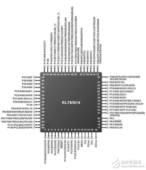
Please refer to Figure 1, which is the pin configuration of the "RL78 family (RL78/G14)". The product has 64 pins. The power supply has 2 pins that are 13/14 (VSS/EVSS0) and 15/16 (VDD/EVDD0).
Pin 13 (VSS) and pin 14 (EVSS0) are connected to GND
Pin 15 pin VDD and pin 16 (EVDD0) are connected to the positive supply
Refer to the “RL78/G14†data sheet (or hardware manual) and you will find “Power Supply VDD = 1.6~5.5 Vâ€. This means that when the power supply voltage is between 1.6V and 5.5V, the normal operation of the microcontroller can be guaranteed. This voltage range is called the operating supply voltage. This range is referred to as the recommended operating voltage range in some microcontroller data sheets.

Figure 1: Pin Connection Diagram for "RL78 Family (RL78/G14)" (64-pin)
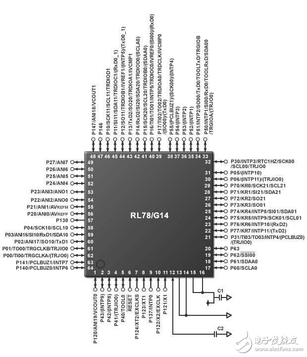
Figure 2 is an example of the power pin connection of the "RL78 family (RL78/G14)".
The C1 connected to pin 15 is called a bypass capacitor. It can prevent the malfunction of the microcontroller caused by the power supply voltage drop caused by the instantaneous large current. A ceramic capacitor of 0.01μF to 0.1μF is usually selected as the bypass capacitor.
The internal circuit operation of the "RL78/G14" is obtained by adjusting the power supply voltage by an internal voltage regulator. The internal circuit operates at 1.8 or 2.1V. To ensure the stability of the internal voltage regulator, capacitor C2 is also connected to pin 12.

Figure 2: Example of power supply circuit connection for "RL78 family (RL78/G14)" (64-pin)
"Total Command" - Oscillation Circuit
As explained in Getting Started 3 of Digital Circuitry, the timing circuit operates synchronously with a rising edge of the clock signal (CK) (signal change from L→H) or a falling edge (signal change from H→L). The single chip microcomputer is composed of a sequential circuit, so an external oscillating circuit is connected externally to provide a clock signal. The clock signal input from the outside of the microcontroller like this is called an "external clock signal".
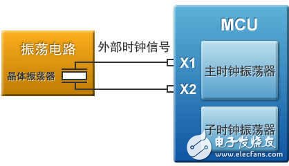
Figure 3 is an example of a single-chip oscillator (RL78/G14) connected to an oscillating circuit. The crystal oscillator is connected between X1 and X2.
It can be seen from the figure that an external clock signal can drive two clock oscillators inside the microcontroller.
The main clock oscillator is mainly used as the operating clock of the CPU.
The subclock oscillator is mainly used as an operating clock for peripheral circuits and real-time clocks.

Figure 3: The role of the oscillator circuit
The "RL78/RL14" (RL78/G14) with a very strong internal peripheral function has a high-precision oscillation circuit with a frequency deviation of only 1%. Therefore, it is not necessary to provide a clock signal from the outside. The internal clock generation circuit on this type of microcontroller is called the "internal oscillator." Since the external oscillating circuit is not required, the design process is reduced and the cost is reduced.
Just like this, as long as the "internal oscillator" is available, you may think that you can "no need to provide a clock signal from the outside." In practice, however, in electronic watches, a more precise crystal oscillator with a frequency that hardly changes with temperature is usually used.
Solar Cable,Pv Cable,Pv Solar Cable,Dc Solar Cable
HENAN QIFAN ELECTRIC CO., LTD. , https://www.hnqifancable.com