PLC is one of the indispensable control methods in the industry. It can be completed by small equipment or large-scale system PLC, and can interact with human-machine interface. It can be done with computer communication. The first PLC is used. In place of the relay control circuit, the PLC has been a multi-function and integrated controller. The most basic timer, counter, analog input or output can be completed by the CPU unit of the PLC. The PLC can be understood as a micro-counter. Used in electrical control.
working principle
The PLC works by means of "sequential scanning, continuous cycling". That is, when the PLC is running, the CPU prepares a program that is stored in the user memory according to the control requirements, and performs periodic cyclic scanning according to the instruction step number (or address number). If there is no jump instruction, the first instruction starts. The user program is executed sequentially one by one until the end of the program, and then the first instruction is returned again, and the next round of new scanning is started. In each scanning process, the sampling of the input signal and the refresh of the output state are completed.
One scan cycle of the PLC must pass the three stages of input sampling, program execution and output refresh.
During the input sampling phase of the PLC: firstly, the on-off state or input data of all the input terminals temporarily stored in the input latch are read in order by scanning, and written into each corresponding input status register, that is, the input is refreshed. , then close the input port and enter the program execution phase.
In the program execution phase of the PLC: each instruction is scanned and executed according to the order in which the user program instructions are stored. After the corresponding operation and processing, the result is written into the output status register, and all contents in the output status register are executed along with the program. And change.
Output refresh phase: When all instructions are executed, the on/off state of the output status register is sent to the output latch during the output refresh phase, and is outputted in a certain way (relay, transistor or inter-well) to drive the corresponding output device to work. .
Characteristics
PLC programming has a wide range of applications, powerful functions and convenient use. It has become one of the main devices of modern industrial automation. It has been widely used in all fields of industrial production, and has been applied in other fields (such as civil and home automation). Rapid development.
In the third draft of the 1985 PLC Standard Draft, the International Electrotechnical Commission (IEC) defined the PLC as follows: "It is an electronic system for digital operation, designed for applications in industrial environments. It is programmable. The program's memory is used to store instructions for performing operations such as logic operations, sequence control, timing, counting, and arithmetic operations, and to control various types of mechanical or production processes through digital and analog inputs and outputs. The programmable controller and its related equipment should be designed according to the principle that it is easy to make the industrial control system form a whole and easy to expand its functions. As can be seen from the above definition, PLC is an industry that uses programs to change control functions. The control computer, in addition to various control functions, has the function of communicating with other computers.
The popularization and application of PLC programming has been rapidly developed in China. It has been widely used in various mechanical equipment and electrical control devices in the production process. The results of a large number of applications of PLC transformation equipment have also emerged in various industries. Understanding the working principle of PLC and having the ability to design, debug and maintain PLC control system has become the basic requirement of modern industry for electrical technicians and engineering students.
Plc programming and application combatBecause there are so many PLC programming softwares, we can't introduce them to you one by one. Therefore, the part related to writing PLC control program in this paper uses the more common Siemens STEP 7-Micro/WIN programming software as an example.
1, fountain control
1) Clear system control requirements
The system requires two buttons to control the three groups of A, B, C nozzles (by controlling the pump motor of the three groups of nozzles), the three groups of nozzles are arranged as shown below.
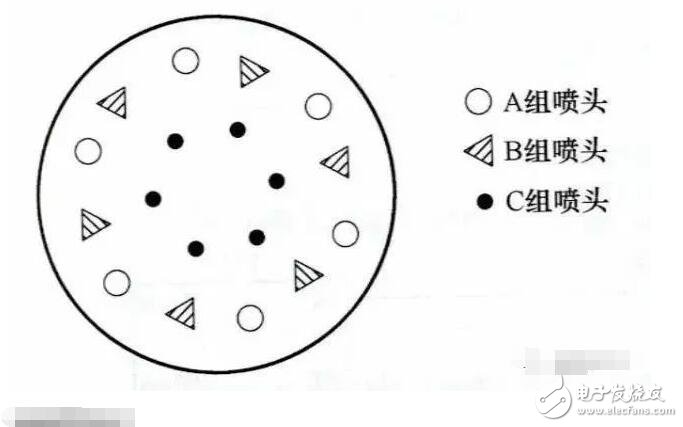
The system control requirements are as follows:
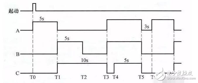
When the start button is pressed, the A group nozzles are sprayed for 5s and then stopped. Then, the B and C groups are sprayed at the same time. After 5s, the Group B nozzles stop, the Group C nozzles continue to spray for 5s and then stop, and then the Group A and Group B nozzles spray 7s. The nozzles of group C are stopped within the first 2s of the 7s, and the water is sprayed within 5s, then the nozzles of groups A, B and C are stopped for 3s at the same time, and the foregoing process is repeated. After pressing the stop button, the three groups of nozzles stop spraying at the same time. The following figure shows the working sequence diagram of the three groups of nozzles A, B and C.
2) Identify the input/output device and assign it the appropriate I/O terminals
The input/output devices and corresponding PLC terminals used for fountain control are shown in the following table:
3) Draw the fountain control circuit diagram
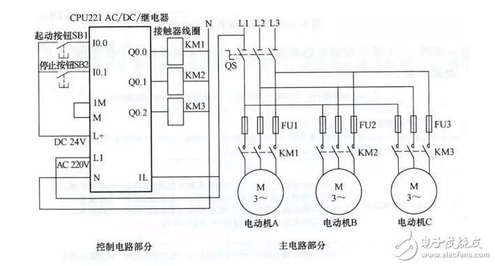
Control circuit diagram
4) Write PLC control program
Start the STEP 7-Micro/WIN programming software and write a ladder program that meets the control requirements. The completed ladder diagram is shown below.
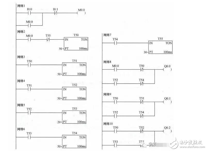
Ladder diagram
The following describes the working principle of the ladder diagram with reference to the control circuit:
1) Start control
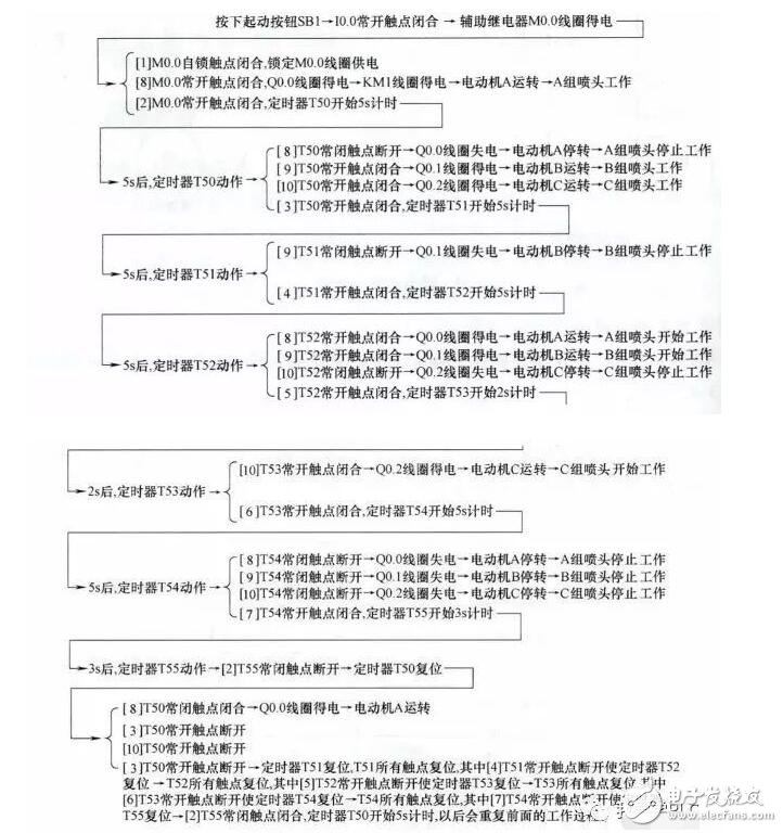
2) Stop control

2. Traffic signal control
1) Clear system control requirements
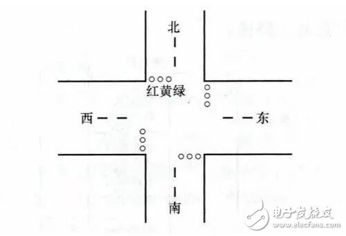
The system requires two buttons to control the traffic light. The traffic lights are arranged as shown below.
The system control requirements are as follows:
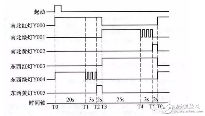
When the start button is pressed, the north and south red lights are on for 25s. In the time when the north and south red lights are on for 25s, the green light of the east and the west lights up for 20s and then flashes 3 times at a frequency of 1 time/s. Then the yellow light of the east and west lights is 2s, and the north and south are red after 25s. The light goes out and the extinguishing time is maintained for 30s. During this 30s time, the red light of the thing is always on, the green light of the north and south lights up for 25s, then it flashes 3 times at 1 time/s frequency, then the north and south yellow lights are on for 2s. Repeat the process later. When the stop button is pressed, all lights are off. The working timing of traffic lights is shown below.
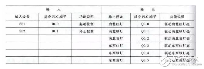
2) Identify the input/output device and assign it the appropriate I/O terminals
The input/output devices and corresponding PLC terminals used for traffic signal control are shown in the table below.
3) Draw a traffic signal control circuit diagram
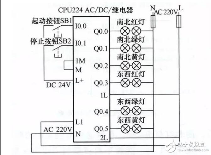
Control circuit diagram
4) Write PLC control program
Start the STEP 7-Micro/WIN programming software and write a ladder program that meets the control requirements. The completed ladder diagram is shown below.
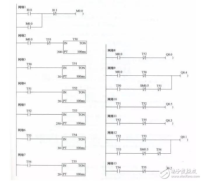
Ladder diagram
In the ladder diagram shown above, a special auxiliary relay SM0.5, called contact-use type special relay, is used, which uses the PLC to automatically drive the coil. The user can only use its contact, that is, draw a ladder diagram. Only its contacts can be drawn. SM0.5 can generate a clock pulse with a period of 1s, and its high and low level durations are each 0.5s. For example, the ladder diagram network 9 is taken as an example. When the T50 normally open contact is closed, the SM0.5 is normally closed within 1s. The point turn-on and turn-off times are 0.5 s, and the Q0.4 coil is energized and the power-down time is also 0.5 s.
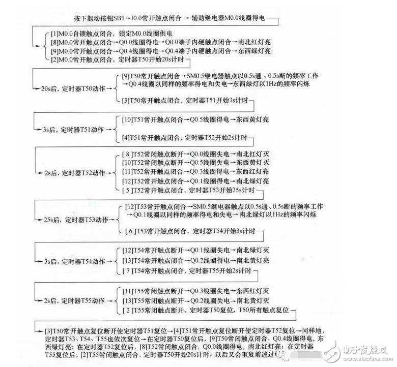
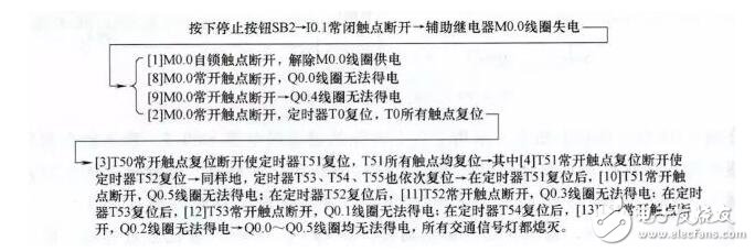
The operation of the ladder diagram is explained below with reference to the control circuit and timing diagram:
1) Start control
2) Stop control
Our company specializes in the production and sales of all kinds of terminals, copper terminals, nose wire ears, cold pressed terminals, copper joints, but also according to customer requirements for customization and production, our raw materials are produced and sold by ourselves, we have their own raw materials processing plant, high purity T2 copper, quality and quantity, come to me to order it!
Cable Terminals
Taixing Longyi Terminals Co.,Ltd. , https://www.longyiterminals.com