In the "Computer Interface Technology" teaching, the chapter on hard disk interface adapters is more difficult to learn, mainly related to the I/O control layer to read and write sectors and use the logical mapping layer to manage data. The content is more abstract, teachers and Students can only teach and learn by imagination. In the scientific research, the author has deepened the understanding of these contents through the development and application of the embedded microprocessor and hard disk interface, laid the foundation for expanding the depth and breadth of this part of the teaching content, and used the combination of theory and practice to teach. The relevant content has been welcomed by students. Therefore, this article is written with the teachers who are engaged in the teaching of hard disk interface technology.
1 ARM system and IDE interface overview
ARM (A dvanced RS IC M ach ines) is a low power, high performance 32-bit processor. The system described in this article is based on the Samsung S3C44B0X. The core of the CPU is ARM 7TDM I, which adopts three-stage pipeline and VON N eumann structure, and has UART, IIC, IIS, S IO interface, ADC, PWM channel, real-time clock, LCD controller and so on.
The hard disk interface structure is mainly divided into an I/O control layer and a logical mapping layer. The I/O control layer includes a physical interface with the ARM to enable query, setup, and read and write of the disk state. It is an IDE interface that is connected according to the A TA standard. Select programmable P IO via the IDE interface or transfer data using the DMA method. This article will introduce the P IO mode transfer, that is, each access to the hard disk needs to be programmed separately.
The logical mapping layer implements logical mapping of directory, file and sector data, as well as storage and modification of data. This part uses the Microsoft FA T standard to construct a linked list for each file's disk block, and manages the entire disk file through the linked table and its index.
In microcomputer applications, because large-volume data is often involved, connecting a large-capacity hard disk through an IDE interface is an effective method when network conditions are not available. If the hard disk is connected according to the A TA standard of AN SI and the data management is performed through the Fat32 file system, the hard disk read and written by the embedded system can also be moved offline to the PC supported by the W in2dow s operating system. The operating system shares hard disk data resources. The methods described in this article can be extended to other microprocessor applications.
2 hardware structure and I / O control layer
The A TA standard describes the IDE hard disk interface in detail.
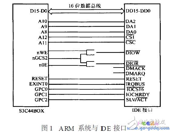
Figure 1 shows the connection in accordance with the A TA specification in conjunction with the P IO transfer characteristics. Since DMA transfer is not used, DMARQ and DMACK are both left floating; /IOCS16 is used to select 16-bit transfer using DD0~DD15 or 8-bit transfer using DD0~DD7; /D IOR and /D IOW are disk drive registers A pair of handshake signals for read and write operations; /C S0 is used to select the command register set, /C S1 selects the control register set. These two signal lines, in combination with DA 0 to DA 2, can access multiple registers of the IDE, such as data registers, status registers, command registers, and so on.

In addition, the A TA standard also has strict definitions for IDE commands, such as 0xEC for confirming the drive and 0xE4 for the read buffer. In P IO mode, the system sends IDE commands to the command register, reads and writes the corresponding data and status registers, and accesses and controls the hard disk.
The operation of the internal data of the hard disk needs to know how it is physically stored. The head, cylinder and sector are the basic structure of the hard disk, and the sector is the smallest unit for reading and writing to the hard disk. There are two internal addressing modes of the hard disk, one is the physical addressing CHS mode, and the other is the logically addressed LBA mode. The physical addressing of the CHS mode is to determine the unique storage unit by cylinder, head and sector number, which is cumbersome. The logical addressing method uses a linear mapping method. The mapping relationship from physical structure to logical block number is as follows:
LBA = (Cylinder number & TImes; number of heads + head number) &TImes; number of sectors + sector number - 1
In this way, the host can directly address the target sector without knowing the physical structure of the hard disk.
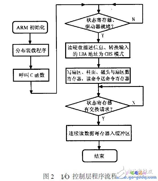
According to the previous description, the control program of the I/O control layer is programmed to query, set and logically address the IDE control register to read and write the specified sectors. Figure 2 is a flow chart for reading a sector of data. The method of writing a sector is similar to that of the sector. The only difference is that the instruction is transmitted and the data flows in a different direction. In addition, when detecting the status register, it is best to add a timeout judgment to prevent the program from falling into an infinite loop.

Plano Concave and Bi-Convex/concave Cylindrical Lens
Plano-concave Cylindrical Lens is an optical product, which is a divergent linear virtual image used to control the size of the light beam in only one direction. Combined with a plano-convex cylindrical lens, it can be used to shape the elliptical beam of a semiconductor laser into a circular beam. Plano-concave cylindrical mirrors can be used in projection systems, imaging systems, optical instruments, and laser measurement systems. Plano-concave cylindrical mirrors are also commonly used to convert a collimated laser source into a line light source, and plano-concave cylindrical mirrors are often used for beam expansion applications. Compared with spherical lenses, cylindrical lenses are more difficult to manufacture.Cylindrical lens is mainly used to change the design requirements of imaging size. For example, convert a point spot into a line spot, or change the height of the image without changing the desired width. The special optical performance of cylindrical mirrors. With the rapid development of high technology, cylindrical mirrors have become more and more widely used.
Concave Cylinder Lens,Cylinder Lens Concave,Convex Cylindrical Lens,Cylinder Rod Lenses
Bohr Optics Co.,Ltd , https://www.bohr-optics.com