1 Introduction
In recent years, with the rapid development of RFID (Radio Frequency Identification) technology, this technology has been widely used in production, logistics, transportation, transportation, medical, anti-counterfeiting, tracking and asset management applications. Currently, the frequency bands used by countries vary, and in North and South America, the passive RFID band is 902MHz to 928MHz. Many workers have done a lot of research work on gap coupling, high isolation and dual polarization, such as the proposed microstrip antenna using slot coupling, and the high isolation between dual polarization and two ports. However, its operating frequency is 5.8GHz. The antenna mentioned has a simple structure and a center operating frequency of 911 MHz, but its impedance bandwidth is relatively narrow. There are also RFID antennas operating in a wide frequency band from 865 MHz to 928 MHz, but this antenna is only suitable for use as a tag antenna.
For microstrip antennas, slot coupling has better design flexibility than other feed mechanisms. Dual-polarized microstrip antennas are also well suited for RFID applications. Therefore, in this paper, we propose a dual-polarized slot-coupled microstrip antenna suitable for RFID applications in North and South America. The microstrip antenna has a higher isolation; the gain of the antenna is approximately 7.5 dBi; the bandwidth has covered the 902 MHz-928 MHz band at VSWR=1.5.
2 antenna design
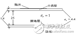
This paper mainly designs a slot-coupled microstrip antenna. The antenna is divided into three layers: the top layer is the dielectric layer, the dielectric layer is the radiation patch; the middle layer is the air layer; the bottom layer is also the dielectric layer, the dielectric layer is the ground layer, and the dielectric layer is the feed. Their parameters are set as follows: the dielectric layer thickness is 1.6mm; their relative dielectric constant is 4.4; in order to increase the bandwidth of the antenna, the thickness of the air layer is selected here to be 25mm. A side view of the antenna is shown in Figure 1.

Figure 1 Side view of the antenna
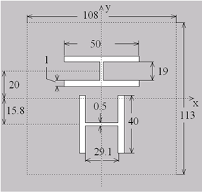
This design uses a single patch. In order to make the antenna resonate at 915MHz, the length of the rectangular patch is 113mm and the width is 108mm. The radiation patch is shown in the dashed box in Figure 2.
The feeding mode of the antenna adopts slot coupling. Two H-shaped slits are dug in the ground plane. The widths of the H-shaped slits are the same (the width of the H-shaped arm and the intermediate arm are 1 mm and 0.5 mm, respectively); the length and width of the slit arm and the intermediate arm are as shown in Fig. 2 (units are mm). Determining a coordinate (x-axis and y-axis) from the centerline of the radiation patch, it can be seen from the figure that the H-shaped slit is symmetric about the y-axis; the relative position of the H-shaped slit and the x-axis is also marked in Figure 2. Out. With slot coupling, high isolation is achieved between port 1 and port 2.

Figure 2 Antenna radiation patch and coupling gap diagram
Below the bottom layer of the antenna is the feed layer. In this design, the feed layer is composed of a 50 om microstrip line with a width of 3.1 mm. The top view of the feed layer is shown in Figure 3. In the figure, t1 = 8.05 mm, and t2 = 11.95 mm.

Figure 3 Antenna feed
Li-po Battery For Electronic Products
Li-Po Battery For Electronic Products,Lipo Battery,Customized Li-Po Battery,Small Lipo Battery
Ji'an Powercom New Energy Co., Ltd. , https://www.expowercome.com