Introduction The MAX9217 / MAX9218 chipset [1] is a transceiver pair. The transmitter (MAX9217) converts parallel data into serial data and sends it to the receiver (MAX9218); the receiver then converts the serial data into parallel data. The chipset is designed to transmit video and control signals from a graphics controller (processor) to an LCD or plasma flat panel display via a pair of low-cost twisted-pair cables (such as the UTP-CAT5 cable commonly used in Ethernet) . The transmission distance can exceed 10 meters. The link structure of the chipset is simple, and the transmission line used is a low-cost cable, which is an ideal solution for video display in automobiles, meters, medical equipment, etc.
The chipset can not only transmit video signals between two points, but sometimes people also want to transmit audio signals at the same time. In this application note, we will discuss how to use the blanking period of the video signal to transmit audio data to the display through the control signal channel. We will also explain how to convert digital audio data into analog audio signals, and give the system structure of the speaker drive at the display panel end. MAX9217 / MAX9218 link function and video data format The MAX9217 serializer has 27-bit parallel input, and the bus rate is up to 35Mbps. Among these 27 bits, 18 bits are video RGB data: 3 primary colors each occupy 6 bits, and the remaining 9 bits are control signals. The first 3 bits of the 9-bit control signal are designated for vertical, horizontal, and RGB data synchronization: VSYNC (C0), HSYNC (C1), and ENAB (C2). The remaining 6 control bits (C3 to C8) are used for other control signals. In this example, we use some of the 6 control bits to transmit audio data. The MAX9217 can convert 18-bit RGB data or 9-bit control data into serial data, and then transmit it through the LVDS link. Control data is sent during the blanking period of the video display, indicated by the RGB data enable signal (ENAB).
After receiving the serial data, the MAX9218 converts it into parallel data in the same format as the MAX9217 input. Similarly, when the MAX9218 outputs parallel data, the bus clock is regenerated according to the timing of the serial LVDS link. Figure 1 shows the structure of the video and control data link settings and connections between the MAX9217 and MAX9218. Figure 2 shows the timing of video data and control data. Depending on the video format, display resolution and link rate, the control duty cycle of RGB data is between 1% and 5%.

Figure 1. MAX9217 / MAX9218 video link settings
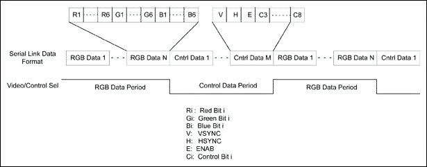
Figure 2. Serial link video data and control data formats Digital audio data types and transmission formats Digital audio data has many different formats. We discuss the three most commonly used formats: sampled digital audio (PCM), MPEG layer 3 audio (MP3) [2] and ATSC digital audio compression standard (AC3) [3].
PCM digital audio is the data format used by CD ROM or DVD. The PCM digital signal is obtained by sampling the audio signals of the left and right channels, with a sampling rate of 44.1 kHz and an accuracy of 16 bits or 32 bits. Therefore, when the precision is 16 bits, the PCM audio data rate is 1.41 Mbps; when it is 32 bits, it is 2.42 Mbps. A 700MB CD can store about 60 minutes of music in 16-bit PCM data format.
MP3 is an audio format used by MP3 players, which compresses and encodes PCM audio data. Stereo MP3 data rate is 112kbps to 128kbps. For this data rate, the decoded MP3 sound has the same quality as CD digital audio. AC3 is a digital audio coding standard for digital TV, HDTV and movies. The data rate after stereo AC3 encoding is 192kbps.
In order to restore the audio signal, the encoded audio data can be sent to the audio decoder chip, which generates PCM digital data, transmits it to the audio DAC, and finally restores it to an analog audio signal. On the contrary, digital audio data without encoding can be directly fed into the audio DAC. (The implementation of this type of system is explained in detail below.)
The commonly used serial audio digital interface for encoding or decoding audio data is Inter-IC Audio Bus (I²S) [4]. Figure 3 shows the I²S interface configuration and timing diagram. The boundary of each audio word is identified by the signal WS. Use configuration mode 1 in our application. On the rising edge of the SCK signal, data is latched to the receiver, but when SCK remains low, no data is received.
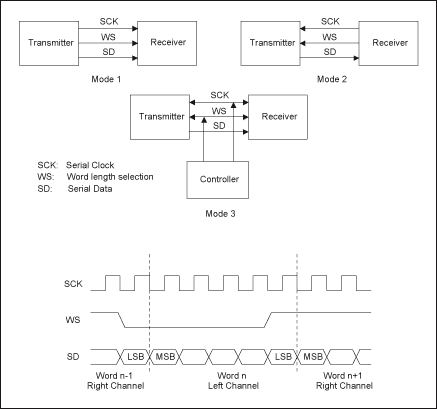
Figure 3. I²S interface configuration and timing
Using the serial link between the MAX9217 and MAX9218 to emulate the I²S interface, audio data can be transferred from the graphics controller end to the remote end. We assign control bits C3 and C4 to SD and WS signals, respectively. For the SCK clock, if you want to send PCM digital audio, you can directly use the pixel clock PCLK_OUT recovered by the MAX9218. For transmitting MP3 or AC3 audio, the control bit C5 can be used to generate a half or lower rate pixel clock for the SCK clock. Figure 4 shows the timing waveforms of these two cases. In order to prevent the receiver from overflowing, most I²S interfaces require throttling control. When sending data continuously, SCK can be set low to directly implement throttling control. Case 1 in Figure 4. During operation, the SCK signal cannot be set low. You can use the chip select pin / CS to turn off the receiver. In this case, Case 1 in Figure 4 assigns C6 to the / CS signal.
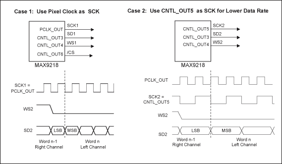
Figure 4. I²S interface control data bit waveform blanking ratio and audio data throughput. Since audio data is transmitted through the blanking period of the video signal, we need to determine the downlink blanking ratio and field blanking ratio for a given pixel frequency fP. Figure 5 shows the line blanking and field blanking periods on the display panel.
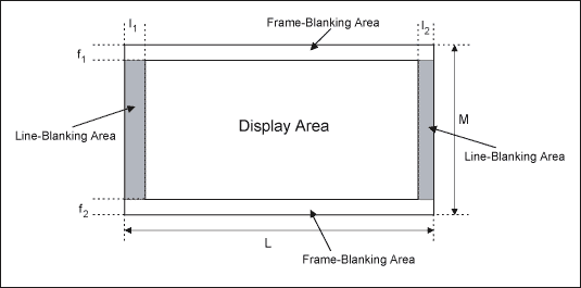
Figure 5. Line blanking and field blanking
Let RL represent the line blanking ratio and RF represent the field blanking ratio. As shown in Figure 5, we can calculate these ratios as follows:
RL = (I1 + I2) / L
with
RF = (f1 + f2) / F
From this, the audio data throughput rate RA is obtained, namely:
RA = (RFδF + (1-RF) RLδL) fP
Where δF and δL are the audio data transmission utilization rate in the blanking period. The utilization rate refers to the proportion of audio data transmission in the entire blanking period, which is the result of throttling control. As an example, the parameters shown in Table 1 set the data rate for 3 types of audio data.
Table 1. Blanking parameter settings for different types of audio data
| Audio Data Type | fP | RA | RB | Data Rate | ||
| 16-Bit PCM Audio Data | 35 | 0.02 | 0.03 | 81% | 82% | 1.41Mbps |
| MP3 | 17.5 | 0.01 | 0.01 | 35% | 38.5% | 128Kbps * |
| AC3 | 17.5 | 0.01 | 0.01 | 50.3% | 60% | 192Kbps * |
* Note: Both MP3 and AC3 audio data contain header files. After considering this information, the actual encoded data rate will be slightly higher [2, 3]. System implementation To play audio signals on the panel side, we need to send PCM data to audio DAC or decode MP3 and AC3 data, and then send it to audio DAC. Since there is no reverse channel to send the handshake signal back to the controller, the decoder host clock must be synchronized with the pixel clock to prevent data overflow or underflow. Figure 6 shows the system structure of the audio playback of coded and uncoded data.
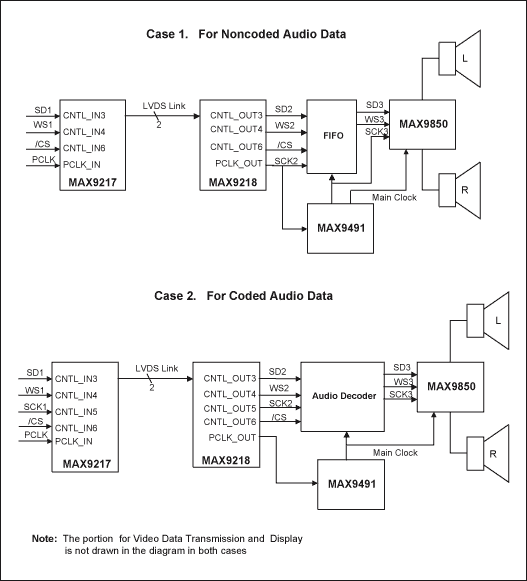
Figure 6. Panel audio playback implementation
In the above structure diagram, the I²S interface is used three times. Starting from the left, the data rates of the first and second I²S interfaces are the same and can reach 35MHz. The third interface—MAX9850 DirectDrive headphone amplifier [5] interface, the rate is fixed at a multiple of the audio sampling rate. The clock SCK2 is fed into the MAX9491 multi-channel clock generator [6], which generates the synchronous clock of the decoder, FIFO and MAX9850. The MAX9491 provides two programmable PLLs including OTP, making it an ideal frequency synthesizer for this application. Case 1 is suitable for providing a graphics controller for decoding PCM audio data, and Case 2 is used for decoding compressed data on the panel side. The throttle control of Case 1 is realized by the / CS pin, and the Case 2 is realized by the idle SCK clock. Comparing these two implementations, we see that Case 1 of PCM audio data does not require too much blanking time (Table 1), does not require the use of an audio decoder chip, and the cost is lower than Case 2. Therefore, if the graphics controller can generate PCM data from encoded audio data streams such as MP3 or AC3, it is recommended to transmit these data directly on the link.
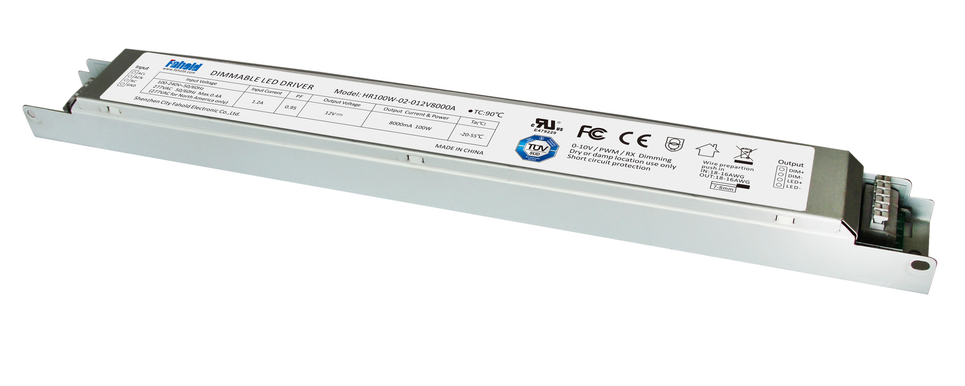
Industrial Strip Lights Led Driver
12V Led Driver , 24V Led Driver, Led Power Driver, Specifically for Industrial strip light, Isolated driver, easy to install, high security, constant Voltage power based. Are generally aluminum materials, long type driver.We have skilled engineers to answer all your questions and enquiries and provide all-round solutions basis on your project(s) and provide technical supporting.
- Standard Linear Lighting, strips lighting
- Cost-effective light-line solution for industry,commercial and other applications
- Good quality of light with high lumen output to meet different requirements
- Easy to order and install,requiring less time,reducing packaging waste and complexity
- Flexible solution
Parameter:
Input voltage: 100-277vac / 100-347V
output voltage: 25-40vdc / 12Vdc / 24vdc
current: 100mA-8000mA.
Power factor: >0.9
Dimming:0-10V / PWM / RX / DALI.
>=50000hours, 5 years warranty.
certificate: UL CE FCC TUV SAA ect.

FAQ:
Question 1:Are you a factory or a trading company?
Answer: We are a factory.
Question 2: Payment term?
Answer: 30% TT deposit + 70% TT before shipment,50% TT deposit + 50% LC balance, Flexible payment
can be negotiated.
Question 3: What's the main business of Fahold?
Answer: Fahold focused on LED controllers and dimmers from 2010. We have 28 engineers who dedicated themselves to researching and developing LED controlling and dimming system.
Question 4: What Fahold will do if we have problems after receiving your products?
Answer: Our products have been strictly inspected before shipping. Once you receive the products you are not satisfied, please feel free to contact us in time, we will do our best to solve any of your problems with our good after-sale service.
Industrial Strip Lights Led Driver
12V Led Driver,24V Led Driver,Led Power Driver
ShenZhen Fahold Electronic Limited , https://www.fahold.com