With the CAN bus being used more and more in the electromagnetic environment where electric vehicles, charging piles, power electronics, rail transit and other electromagnetic environments are relatively harsh, the problem of signal interference has seriously affected the user's trust in the CAN bus. How can we resist interference? This article shows the six "military regulations" of the anti-interference of Zhiyuan electronic CAN bus.
In the era of gasoline vehicles, the CAN bus encountered less interference, even if there are some relays and solenoid valve pulses, it will not have a big impact, a little twisted processing, can achieve zero error frames.
However, in the era of electric vehicles, the influence of high-power equipment such as inverters, motors, and chargers on CAN is enough to interrupt communication or damage the CAN node, as shown in Figure 2 and Figure 2, which is the CAN waveform interfered by the inverter.
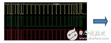
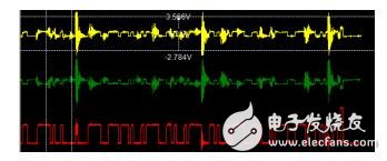
Figure 1 Before the interference Figure 2 After the interference
In the face of interference, manufacturers of various automobile factories, parts factories, and test and diagnostic equipment have all studied the "prejudice" of anti-interference to ensure the stable operation of CAN. This article introduces the anti-jamming 6 “military regulations†based on the 15-year CAN field troubleshooting experience of Guangzhou Zhiyuan Electronics Co., Ltd.
1. CAN interface increases isolation and protectionInterference not only affects the signal, but more serious will cause the board to crash or burn, so the isolation of the interface and the power supply is the first "military regulation" to resist interference. The main purpose of isolation is to avoid the ground return to burn the board and limit the amplitude of the interference, to protect the controller from crashing. As shown in Figure 3, when there is no isolation, the ground potentials of the two nodes are inconsistent, resulting in a return current, resulting in a common-mode signal. The CAN's anti-common-mode interference capability is -12~7V. If the difference is exceeded, an error occurs. If the common mode difference exceeds ±36V, burn the transceiver or board.
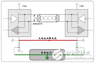
Figure 3 Ground reflow without isolation
After adding the CTM1051KAT isolation module, as shown in Figure 4 and Figure 5. The ground return is isolated, limiting the magnitude of the disturbance.
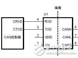
Figure 4 CTM1051KAT isolation module

Figure 5 isolated ground return
After adding isolation, is everything all right? Certainly not, isolation is only a barrier. If the interference intensity is high, such as reaching a 2KV surge, the isolation will be destroyed. Therefore, in order to achieve a higher level of protection, it is necessary to increase the anti-surge circuit. As shown in Figure 6, it is the standard anti-surge protection circuit of Zhiyuan Electronic High Speed ​​Bus.


Figure 6 signal protection circuit
This protection circuit can reach 4KV surge without damage, but note that if you want to pass the 2500VDC withstand voltage test, you need to remove the GDT and R3 to prevent the high voltage breakdown from causing the test to fail.
2. CAN line increases the degree of twisted pairIn order to improve the anti-interference ability, CAN bus adopts CANH and CANL differential transmission. The effect is that after encountering interference, it can be “same as aboveâ€, and finally the differential value of CANH-CANL remains unchanged. As shown in Figure 7.
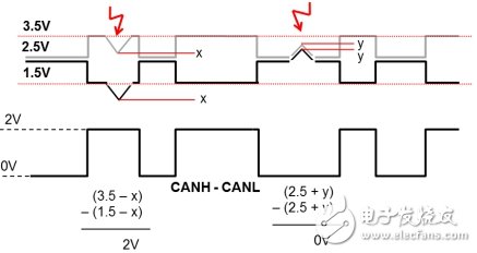
Figure 7 Schematic diagram of differential anti-jamming
However, this anti-interference ability must be such that CANH and CANL are closely tied together, otherwise the received interference intensity will be different, which will cause the differential signal to be interfered. Therefore, CANH and CANL should be tightly twisted together. Generally, the twisted pair is only 33 twists/meter, and in the case of strong interference, the twistedness should exceed 55 twists/meter to achieve better anti-interference effect. In addition, the core cross-sectional area of ​​the cable is greater than 0.35~0.5 mm2, and the line-to-line capacitance of CAN_H to CAN_L is less than 75 pF/m. If shielded twisted pair is used, the capacitance of CAN_H (or CAN_L) to the shielding layer is less than 110 pF/m. The cable impedance can be better reduced to reduce the amplitude of the jitter voltage during interference.
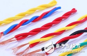
Figure 8 twisted pair
3. CAN line guarantees shielding effect and correct groundingThe shielded CAN line can withstand the interference of the electric field well, which is equal to the entire shield layer is an equipotential body, to avoid interference of the CAN wire. As shown in Figure 9, for a standard shielded twisted pair, CANH and CANL are wrapped by aluminum foil and an oxygen-free copper wire shield mesh, as shown in Figure 9. It should be noted that the connection to the connector allows for cables that are shorter than 25 mm to be twisted without twisting.
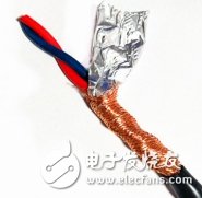
Figure 9 Shielded twisted pair
A better CAN shielded wire has two shield layers, called a double-layer shielded wire, in which the CAN_GND of the inner layer is connected to the ground of the CAN transceiver, and the outer shield is connected to the ground of the outer casing. The inner layer can balance the ground potential of the signal, suppress common mode interference, and reduce the error frame, but the damage rate of the transceiver will increase when the interference is strong; the outer layer can discharge the charge to the earth, as shown in FIG.

Figure 10 double shielded wire
After using the shielded wire, the shielded wire does not work until the shield is not well grounded. So we have to choose a grounding method. Generally speaking, the single-point grounding of the shielding layer can avoid ground reflow (current generated by different ground potentials at different positions), and multi-point grounding can accelerate the discharge of high-frequency interference signals. Therefore, it is necessary to select a suitable grounding method according to the actual situation. As shown in Figure 11.
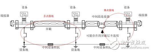
Figure 11 shielding layer grounding method
In the application of CAN, since the distance is generally far away, most of them adopt the principle of single-point grounding of the shielding layer. Find a point on the trunk line and directly ground the shielding layer with wires. This point should be the point with the least interference. This point is located near the center of the network.
4. CAN line is far away from interference sourcesKeeping away from the interference source is the simplest anti-interference method. If the CAN line and the strong electric interference source are far away from 0.5 m, the interference will not be affected. However, in the actual wiring, the space is often too small and has to be mixed with the strong electric power. As shown in Fig. 12, for the driving system of a new energy vehicle, the CAN line and the driving line are mixed together, resulting in great interference. As long as the drive line parallel to the CAN has a current change of 2 A/sec, a strong magnetic field is coupled and an interference pulse appears on the CAN line. Therefore, the CAN line must be kept away from the cable whose current will change drastically. Such as relays, solenoid valves, inverters, motor drive lines, etc.
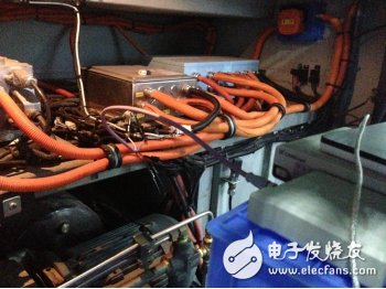
Figure 12 wiring problem
To solve this problem, we can only try to ensure that the strong and weak power are bundled separately, and try to stay away from each other. It is really difficult to avoid, but also to cross vertically, nor parallel wiring.
5. Increase the magnetic ring or common mode inductanceThe use of anti-jamming magnetic rings is designed to attenuate the effects of interference at specific frequencies. As shown in Figure 13, the effect of the magnetic ring is increased. The CAN differential cable can be added together with two wires or added separately at a single end.
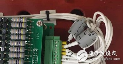
Figure 13 Adding a magnetic ring
The effect of the magnetic ring can greatly reduce the interference intensity of a specific frequency. Before adding the magnetic ring, the CANScope or oscilloscope FFT fast Fourier change function is needed to test the frequency of the highest interference, and then the magnetic ring of the corresponding frequency is customized to the magnetic ring manufacturer. . As shown in Figure 14. To increase the result of the FFT before and after adding the magnetic ring. It can be seen that the interference intensity is significantly reduced.
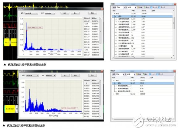
Figure 14 Effect after adding a magnetic ring
It should be noted that when adding a magnetic ring or a common mode inductor, it cannot be added arbitrarily. If the frequency is not correct, it will affect the normal signal communication.
6. CAN is converted to fiber transmissionThe ultimate means of anti-jamming is to convert CAN into fiber transmission, which is a transmission medium that cannot be electromagnetically interfered. If the first five anti-interference methods can not solve the interference problem, CAN can be converted into optical fiber to achieve "invulnerability". As shown in Figure 15. In order to use the optical fiber backbone network of the combination of CANHub-AF1S1 and CANHub-AF2S2 of Zhiyuan Electronics.
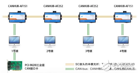
Figure 15 Fiber optic backbone transmission using fiber optic converters
Zhiyuan Electronics has nearly 20 years of CAN bus system solutions, forming the most complete family of CAN bus devices in the product range. With a team of experienced CAN fault diagnosis and testing, we can provide customers with a full range of technical service support.
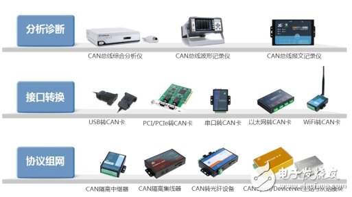
Figure 16 Zhiyuan Electronic CAN Solution Family
Pool Water Pump,Pump Swimming Pool,Dc Pool Pump Motor,Dc Brush Solar Pump
Wuxi Doton Power , https://www.dotonpower.com