[Preface] This article will discuss various OLED technologies and appropriate bias supply circuits, and the choice of OLED technology and drive methods will also affect the power supply circuit requirements. The challenge for engineers is how to choose the most appropriate power supply circuit to support battery-powered portable devices, as well as the needs of specific OLED displays. Functionally advanced displays are becoming an important feature of today's consumer electronics products. The role of these new displays often reinforces the user's impression of the overall product, and such an impression ultimately determines how successful the product will be in the market. The impression of new displays is especially important when users are faced with mobile phones and pocket computers, as high-resolution color screens have become a must-have feature for these products.
A variety of new display technologies are expanding their market share, including new OLED displays, with ultra-high contrast values, fast response times and a wide viewing angle. Like other new technologies, vendors are using different LED materials (polymer or small molecule), active or passive matrix control, current and voltage drive technology, and different bias supply circuits to evaluate and manufacture different solutions.
This article will discuss various OLED technologies and appropriate bias supply circuits, and the choice of OLED technology and drive methods will also affect the power supply circuit requirements. The challenge for engineers is how to choose the most appropriate power supply circuit to support battery-powered portable devices, as well as the needs of specific OLED displays.
Advantages and disadvantages of OLED technology
The wide viewing angle and good color saturation are the main advantages of OLED displays. In this respect, they are far superior to other technologies such as liquid crystal displays. In addition, OLED displays are also self-illuminating technologies, so not only do not require backlighting. It also provides faster response times than liquid crystal displays to support multimedia applications. There are two types of OLED materials on the market, namely small molecules and light-emitting polymers. Compared with standard LEDs, the circuit parameters of these two technologies are similar, and their luminous intensity is determined by the forward bias current of the LED. The pixel brightness of a liquid crystal display is determined by the voltage applied to the liquid crystal pixels.
Another advantage of OLED displays is that they can use existing substrate technology, which is exactly the same as that of thin film transistor (TFT) liquid crystal displays. Active matrix OLED displays can use amorphous silicon (a-Si) or low temperature polysilicon ( TFT substrate of LTPS).
One of the main challenges of existing OLED technology is its lifetime, which is due to the fact that the RGB color decay speed is not the same, especially when most of the display content is white, it needs to send these three primary colors simultaneously. The same brightness. Affected by these color limitations, monochrome displays have become the earliest displays on the market, and full-color displays are only used for applications that turn off the display for most of the life of the product.
The first full-color display is used in digital cameras, but for portable products that use batteries, full-color displays still have problems. OLED displays must compete with liquid crystal displays for power consumption, and they consume far less power than OLED displays for applications that do not require backlighting for liquid crystal displays. If the backlight of the liquid crystal display is activated, it will determine whether the OLED needs more power consumption according to the display content; if the display content is mostly white, the power consumption of the OLED will still exceed that of the liquid crystal display, but with the "white" picture Content is gradually reduced, and power consumption differences will no longer be an issue.
The use of OLED displays outdoors is another challenge for OLED technology. Since such a screen starts to emit light when it is hit by a photon, when the OLED display is used outdoors, the contrast of the screen is lowered, and the readability is also deteriorated.
The shortcomings of the OLED technology make them more suitable for small screens of portable devices, but as the technology matures, it can also be applied to large displays. In the short term, notebook computers or desktop monitors are too difficult for OLEDs because RGB colors experience different aging speeds when displaying a large amount of "white" image content. However, in the application of TV panels, the future technology of OLED is extremely promising, because such applications do not need to display a large amount of "white" image content.
Passive matrix displays require a set of power boost converters
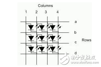
Matrix OLED screens are the mainstream of the current market, mainly used for mobile phones, most of which are external screens for shell-type mobile phones. These monochromatic or two-color passive matrix displays are ideal for OLED technology that is still in its infancy. Figure 1 is a simplified schematic of such a display, which is addressed in a manner similar to a standard passive matrix liquid crystal display. The main difference is that the OLED is a current-driven device, so the driving circuit of the OLED display is different from the liquid crystal display.

Figure 1: Simple schematic of a passive matrix OLED display
A moving matrix OLED display requires a set of positive voltages as its power supply or bias. This set of positive voltages is very similar to the voltage used in liquid crystal displays. It must provide low power consumption and high efficiency, and the solution must be very compact. small. Depending on the size and resolution of the display, the OLED driver component requires a voltage between 15V and 20V, so an inductive boost converter is the ideal solution.
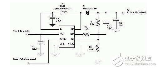
Electrical isolation between the input and output is another important requirement for OLED bias supply, which is important when selecting a power supply. The Schottky diode used in the standard boost converter provides a direct path from input to output that makes the output voltage approximately equal to the input voltage; however, if the application requires a power sequencing function that is turned on or off, or is in shutdown mode This path is the source of the problem by minimizing leakage current. The component shown in Figure 2 uses a built-in MOSFET switch to disconnect the input and output.

Figure 2: Boost converter isolates the input and output of an OLED display
Active matrix display requires positive and negative bias power supply
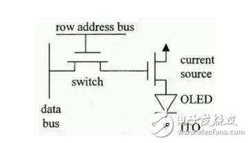
If the application requires higher resolution, larger display area, higher contrast, and faster response time, they can use the active matrix OLED display shown in Figure 3.

Figure 3: Simple schematic of an active matrix display
The turn-on and address of the OLED pixel is controlled by an active switch, which is made up of a thin film transistor. It is manufactured in exactly the same way as a TFT liquid crystal display: the current source has been simplified to require only one MOSFET in series with the OLED. Some designs use a voltage-driven architecture, while others use a current-driven architecture. All designs require two to four or even more integrated thin-film transistors.
To overcome the different aging speed problems of different color OLED pixels, some solutions integrate a photo transistor in the circuit to set a larger OLED current to avoid the pixel brightness decreasing with time. Low-temperature polysilicon (LTPS) substrates have a small component structure, so it would be an advantage if engineers wanted to make more active components on the substrate. At present, there are two technologies used for such substrates, namely low temperature polysilicon and amorphous silicon.
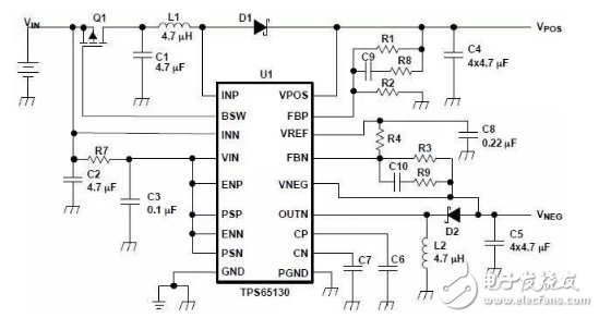
In addition to providing positive and negative voltages as the power source for the video signal driver, the bias power supply circuit of the active OLED display must also provide a bias voltage to enable the row select thin film transistors to be turned on and off. Inductive boost converters are the most suitable solution due to the high voltage of the bias voltage. To minimize the size of the solution, the fully integrated boost converter shown in Figure 4 uses an inverter to provide a negative voltage in addition to providing a positive voltage.

Figure 4: Single component provides both positive and negative voltages
In order to minimize the leakage current in shutdown mode and provide power sequencing for positive voltages, the components in Figure 4 control another external MOSFET transistor (Q1) in a SOT-23 or smaller package. This component uses a Li-Ion battery as the input power supply (2.7V to 5.5V) and provides output voltages up to +15V and -15V, as well as an integrated 800mA/2A switching current limit function that allows output currents up to 200mA. .
In order to provide power to the OLED display, the output voltage must be small and the switching frequency must be fixed to minimize the distortion and cross-coupling effects of the OLED display. In this regard, the TPS6513x with a 1.38MHz fixed-frequency PWM mechanism is ideal for providing power to OLED displays. Although providing a high-accuracy regulated output is particularly important for voltage-driven liquid crystal displays over the load current range, it does not pose much of a problem for current-driven OLED displays.
Some monitors require large currents when used outdoors, currents are reduced indoors, and they must provide high power efficiency over a wide range of load currents. Since the standard boost converter can only achieve optimum efficiency at the target load current, the TPS65130 additionally provides a user-selectable "power saving mode" that reduces the switching frequency and quiescent current, allowing the component to be High operating efficiency is maintained over the load current range.
As OLED technology matures, its market share will continue to rise. The potential of this technology in mobile phones, digital cameras and pocket computer screens is amazing. Active matrix displays may replace passive matrix displays in the market, OLED display driver components will become more advanced, and OLED bias power supply circuits will begin to be miniaturized and specialized, which is part of the solution described in this article. Have been discussed. For power supply component technology, the main challenge is how to provide both high efficiency and smallest volume solutions.
What is a slip ring?
A slip ring is an electromechanical device that allows electrical current to flow through a rotating assembly. It is often used in conjunction with a commutator to create an electrical connection in a rotating system. The device consists of a number of contact rings mounted on the rotating assembly and two or more stationary contacts. When the rotating assembly is rotated, the contact rings pass by the stationary contacts, creating an electrical connection.
Types of slip rings
A slip ring is an electromechanical device that allows the transmission of power and electrical signals through a rotating assembly. Slip rings are commonly used in applications where it is not possible or practical to make a permanent electrical connection, such as on a rotating antenna, wind turbine, or radar dish. There are many different types of slip rings available, each with its own set of benefits and drawbacks. Some of the more common types of slip rings include fiber optic slip rings, rotary unions, and contactless slip rings.
Advantages of custom slip rings
When it comes to slip rings, custom-made ones have a lot of advantages over the standard, off-the-shelf variety. Custom slip rings are designed specifically for your application, so you can be sure they`ll meet all your needs. They`re also made to order, so you can get exactly the features you want. And because they`re made specifically for you, they`re often less expensive than generic slip rings.
Disadvantages of custom slip rings
In many industrial and commercial applications, a custom slip ring is the best way to transfer power and/or data between two systems. While custom slip rings offer many advantages, they also have some disadvantages. In this article, we will discuss the disadvantages of custom slip rings.
One disadvantage of custom slip rings is that they are often more expensive than other types of electrical connectors, such as wire harnesses or connectors. Additionally, custom slip rings can be difficult to install and may require specialized tools. Another disadvantage is that custom slip rings are not always as reliable as other types of electrical connectors. They can fail prematurely if not properly maintained or used in the correct application.
Conclusion: When to use a custom slip ring
A custom slip ring is an electromechanical device that allows for the transmission of electrical signals and power between rotating and stationary components. The use of a custom slip ring can be beneficial in a number of ways, including improved performance, increased efficiency, and longer life. In some cases, a custom slip ring may be the only option available for achieving the desired results. When considering a custom slip ring as an option for your application, it is important to understand the different factors that will impact its performance.
Custom Slip Ring,Rotary Joint Price,High Pressure Rotary Joint,Moflon Rotary Union
Dongguan Oubaibo Technology Co., Ltd. , https://www.sliprob.com