CATV Upstream Amplifier Selection Guide
Abstract: This selection guide provides the differences between the MAX3503, MAX3505, MAX3507, MAX3509, MAX3510, MAX3514, and MAX3516 upstream drive amplifiers in cable modem and CATV systems. These devices comply with DOCSIS and EuroDOCSIS standards.
This application note compares the features and functions of Maxim CATV upstream amplifiers. Six kinds of devices are described in this article, and their main functional differences and operating characteristic curves are given.
The MAX3510 immediately became the industry standard for CATV upstream amplifiers. The chip uses differential input / output mode and is current driven output. The MAX3510's burst on / off transient levels are far superior to the DOCSIS standard (see Figure 1). When the output is 60dBmV, the MAX3510 can guarantee a maximum transient level of 37mVp-p, and the typical value can reach 7mVp-p, which is far below the limit of 100mVp-p set in DOCSIS. In addition, the MAX3510 also provides an index that is better than the DOCSIS emission-inhibited mode with an in-band noise of less than -59dBmV. In the operating temperature range of 0 ° C to + 85 ° C, the MAX3510 has a maximum output noise of- 70dBmV. 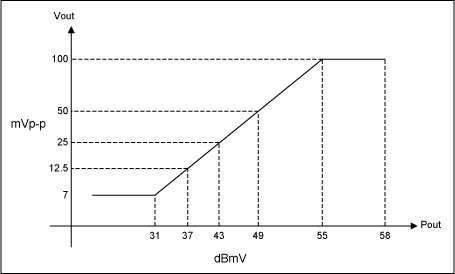
Figure 1. DOCSIS-defined burst on / off transient levels
The MAX3514 is designed for the extended frequency range of Euro-DOCSIS (65MHz). Like the MAX3510, it also uses a differential input / output mode and is a current-driven output. The chip has more stringent gain characteristics over the entire temperature and gain code range (see Figure 2). A typical gain variation range of ± 1dB (fixed gain code, 0 ° C to 85 ° C) allows 1dB in-band fluctuations in the duplex filter. This makes it easier for cable modem firmware to correct power levels. The MAX3514 fully complies with DOCSIS and the dual-design EuroDOCSIS / DOCSIS cable modem specifications. MAX3514 is replacing MAX3510 as the new industry standard. The pins of the MAX3514 and MAX3510 are fully compatible. 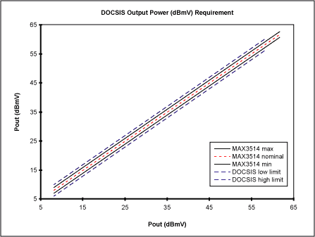
Figure 2. DOCSIS-specified upstream power level and MAX3514 performance
The MAX3514 provides better performance than the DOCSIS emission-inhibited mode in which the in-band noise is less than -59dBmV. The MAX3514 has a maximum output noise of -71dBmV in the emission-inhibited mode within the operating temperature range of 0 ° C to + 85 ° C. DOCSIS requires an output power range of 50dB (see Figure 3) and a gain difference of 1dB. 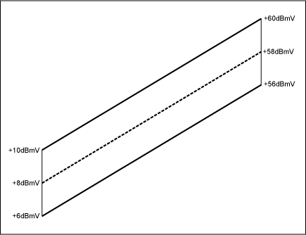
Figure 3. DOCSIS specified upstream power level
In practical applications, a wider range may be needed to overcome the gain loss and duplexer loss of the amplifier at the 42MHz band edge (see Figure 4). Of course, this depends on the specific design characteristics of the duplexer. 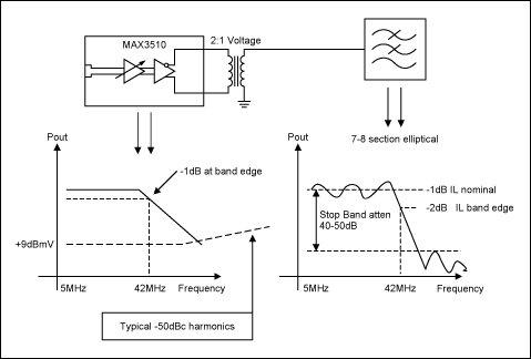
Figure 4. Band edge loss
The MAX3514 can provide a gain control range of 56dB and a gain difference of 0.5dB. The MAX3514 has good harmonic characteristics. The specifications given in the data sheet are: when outputting 61dBmV, if the input frequency is 33MHz, the second harmonic distortion is -55dBc; if the input frequency is 22MHz, the third harmonic distortion is -55dBc. Harmonic characteristics improve the low-frequency performance of the system, and it is easy to meet DOCSIS specifications for in-band spurious signal radiation (see Figure 5). 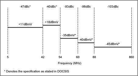
Figure 5. DOCSIS in-band spurious emissions
The MAX3509 has the functions provided by the MAX3510, and it also has a fairly high output swing (+ 68dBmV). The chip is characterized by a voltage-driven, near-zero impedance differential output, which is suitable for systems that provide external bus termination (eg, through a 10dB coupler). Can use 1: 1 output transformer, the chip can provide the highest drive level under a given power supply. The standby current is only 7.8mA, which greatly reduces the average power loss in power sensitive systems.
The MAX3517 is essentially the MAX3514 with an external output matching resistor. This provides a flexible choice for custom tuned output transformers and unique duplexer source impedance.
The MAX3516 is used to handle the high output power of cable phones and set-top boxes. It basically adds 3dB gain and large size, thermally enhanced package 20-pin TSSOP-EP on the basis of MAX3514. The exposed pad is conducive to heat dissipation and improves the reliability of the chip.
The MAX3503 drives 61dBmV (QPSK) into a 75Ω load. By using a 3.3V supply a 5V regulator and associated power supply circuitry may be eliminated resulTIng in reduced BOM cost. Gain control is available in 0.5dB steps. The device operates over a frequency range of 5MHz to 65MHz.
The MAX3505 is basically a MAX3503 designed to operate with a 5V supply. The MAX3505 has very good linearity and can deliver + 64dBmV.
The MAX3507 is capable of generaTIng + 63dBmV output. The on-chip anTI-alias lowpass filter saves BOM cost and significant space reducTIon. The optional positive slope generator provides system design flexibility.
In the new design, MAX3532 is not recommended, and can be replaced by MAX3510, MAX3514, and MAX3516.
| Market | Part | Features | |||
DOCSIS Cable Modem | MAX3510 | 56dB gain range, 1dB gain step, 20QSOP | |||
EuroDOCSIS Cable Modem | MAX3514 | Pin-for-pin compatible with MAX3510, 0.5dB gain step, tight gain control, 20QSOP | |||
DOCSIS / EuroDOCSIS Cable Modem (Module) | MAX3514 | Pin-for-pin compatible with MAX3510, 0.5dB gain step, tight gain control, 20QSOP | |||
US Set-Top Box | MAX3510 | 56dB gain range, 1dB gain step, 20QSOP | |||
European Set-Top Box | MAX3514 | Pin-for-pin compatible with MAX3510, 0.5dB gain step, tight gain control, 20QSOP | |||
DVB Set-Top Box | MAX3516 | 20TSSOPP-EP | |||
Cable Telephony (Circuit Switched) | MAX3509 | 68dBmV, low output impedance, 20TSSOP-EP | |||
Cable Telephony (Packet Switched) | MAX3514 | Pin-for-pin compatible with MAX3510, 0.5dB gain step, tight gain control, 20QSOP | |||
Open Cable Set-Top Box | MAX3516 | 20TSSOPP-EP | |||
DOCSIS 2.0 | MAX3503 | 3.3V supply, 20QFN | |||
MAX3505 | + 64dBmV, 20QFM | ||||
MAX3507 | Positive slope generator, Integrated anti-alias filter, 28QFN | ||||
MAX3514 | Industry standard, 20Q50P | ||||
MAX3516 | PHigh reliability exposed paddle 20T SSOPP-EP package | ||||
| Power (dBmV) | Harmonics | Supply Voltage | Part | |||
| 66 | -56dBc 2HD, f = 33MHz Pout = + 66dBmV -53dBc 3HD, f = 22MHz Pout = + 66dBmV | 9 | MAX3509 | |||
64 | -55dBc 2HD, f = 33MHz Pout = + 64dBmV -50dBc 3HD, f = 22MHz Pout = + 64dBmV | 5 | MAX3516 | |||
61 | -55dBc 2HD, f = 33MHz Pout = + 61dBm -55dBc 3HD, f = 22MHz Pout = + 61dBmV | 5 | MAX3514 | |||
59 | -55dBc 2HD, f = 33MHz Pout = + 59dBmV -54dBc 3HD, f = 22MHz Pout = + 59dBmV | 5 | MAX3510 | |||
63 | -58dBc 2HD, f = 33MHz Pout = + 63dBm -53dBc 3HD, f = 22MHz Pout = + 63dBmV | 5 | MAX3507 | |||
64 | -55dBc HD2, f = 33MHz Pout = + 64dBmV -55dBc HD3, f = 22MHz Pout = + 64dBmV | 5 | MAX3505 | |||
61 | -55dBc HD2, f = 33MHz Pout = + 61dBm -55dBc HD3, f = 22MHz Pout = + 61dBmV | 5 | MAX3503 | |||
Epoxy Resin Solar Panel,Watt Flexible Solar Panel,Epoxy Resin Solar Module,Resin Encapsulated Solar Panel
Shengtian New Energy (Shenzhen)Â Co., Ltd. , https://www.stenergysolar.com