In recent years, the development of servo system has always been the development of stability, responsiveness and precision, which is the most important factor in the user's use. In the machine tool servo system, robot control system, radar antenna control system and other occasions, most of them are controlled by DC servo motor and DC servo controller. In these control fields, the servo control system [1] is mainly controlled by the position or angle of the load. With the rapid development of inverter technology, AC variable frequency transmission in servo system has been widely used due to its high power factor, fast response speed, high precision and suitable for use in harsh environments. This paper proposes a digital variable frequency servo system based on high-performance single-chip MSP430F149, frequency converter and variable frequency motor, and introduces digital PID algorithm into this system, so that the system obtains good static and dynamic performance of the system.
1 frequency conversion servo system function
In order to achieve reliable operation, good static and dynamic performance requirements of the variable frequency servo system, its functions are as follows:
1) Precise servo control function
High precision, high speed and high power are the development trend of servo system. The system uses high-speed single-chip microcomputer as the core controller to control the inverter to achieve higher precision of servo system control.
2) Communication function
The communication between the MCU and the host computer must ensure the normality and correctness of the communication. The MCU will receive the control command from the host computer and compare it with the sampled feedback signal to obtain the offset control amount. Only when the corresponding offset is obtained, the MCU will convert the MCU. The device outputs the corresponding control signal.
3) Feedback volume accurate acquisition function
The accuracy of feedback quantity acquisition is directly related to the control accuracy. The system uses the variable M/T method to sample the speed of the servo motor. The sampling accuracy is more accurate than the M method and the T method, thus ensuring more precise control.
2 system hardware design
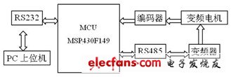
The system is composed of single-chip MSP430F149 as the core controller [2], integrated inverter, variable frequency motor, sampling encoder and PC upper computer. The system block diagram is shown in Figure 1.

Figure 1 system block diagram
The control process is as follows: the single chip microcomputer MSP430F149 controls the function modules of the coordination system; the PC host computer transmits the control signal to the MSP430F149 through the serial port UART0, and the single chip computer processes the feedback signal, and processes the processed data with the control signal from the upper computer. Comparing with each other, the error amount is obtained, and the error amount is subjected to the corresponding operation to obtain the servo system control amount; MSP430F149 will get the control amount directly converted into RS485 signal output to the inverter through the serial port UART1, and the inverter generates the frequency conversion according to the received control signal. The power signal of the voltage is used to drive the motor to complete the desired action; at the same time, the upper computer obtains the printing report by obtaining the speed and system parameters of the variable frequency motor through the serial port UART0 of the MSP430F149, which is a good man-machine operation interface for the operator.
2.1 single chip unit
MSP430F149 is the core controller of the variable frequency AC servo system, which completes the transmission of system control signals and measurement signals and complex control decisions, coordinates the work of each module, and receives and recognizes the operation control commands. This microcontroller is an ultra-low-power microcontroller with a 16-bit architecture, 16-bit CPU integrated registers and a constant generator for maximum code efficiency. It includes two built-in 16-bit timers, a fast 12-bit A/D converter, two universal serial synchronous asynchronous communication interfaces and 48 I/O ports. The chip contains 60KFLASHROM and 2KB RAM. This design is a real-time control system that requires real-time data collection and transmission. The 60KFLASH memory in MSP430F149 can meet the needs of system program for programming storage space. The internal data RAM (2K) ensures real-time data acquisition, processing and transmission. 48 digital peripheral ports conveniently realize data transmission and control with peripheral devices. The 16-bit architecture ensures that the system can perform complex control decisions, while the dual-serial UART satisfies the real-time communication needs of the controller with the host computer and the inverter.
2.2 photoelectric encoder and variable M / T speed MSP430F149 internal implementation
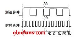
The accuracy control of the servo system mainly depends on the measurement accuracy of the motor speed signal. This system uses an incremental photoelectric encoder as the motor speed as the detection component. The more common methods of measuring the speed of electric encoders are M method, T method and M/T method. The M method is to measure the number of pulses output by the photoelectric encoder in a predetermined time interval to obtain the speed value of the measured motor speed, which is suitable for high-speed measurement occasions. The T method is a method of measuring the interval between adjacent two pulses to determine the speed of the motor under test. This method is less accurate when measuring at high speeds, so it is generally only suitable for low speed measurement. The M/T method determines the rotational speed by simultaneously measuring the detection time and the number of pulses occurring during this detection time. It has better speed measurement accuracy in the whole speed range, but with low frequency, it requires a long measurement time and can not meet the fast dynamic response performance index of the servo system [2]. In recent years, the M/T speed measurement method has been gradually used. It means that not only the photoelectric encoder pulse M1 and the high frequency clock pulse M2 are changed with the motor rotation speed during the speed measurement process, but also the detection time Tg is also changed, which is always equal to The sum of the pulse cycles of the photoelectric encoder M1 (the speed measurement principle is shown in Figure 2). The size of Tg is taken from the high frequency clock pulse M2, and the motor speed meter can be determined by the following formula [3].

Where: M1 is the preset pulse number; M2 is the high frequency clock pulse number; fc is the high frequency clock frequency; λ is the photoelectric encoder multiplication factor; P is the photoelectric encoder line number.

Figure 2 Variable M/T method of speed measurement
When the motor runs at low speed, the detection time Tg of the M/T method is obviously shorter than that of the M/T method. It can be seen that the variable M/T method speed measurement can meet the requirements of the control system for the accuracy and real-time performance of the speed measurement. .
The MSP430F149 internal timers A and B can be used to measure the motor speed change M/T method, which can simplify the design of peripheral circuits and reduce system power consumption. Timer A counts the external photoelectric encoder pulse, timer B counts the internal high frequency clock of the system; timer A operates in 16-bit counting mode, and loads the measured value M1 into the register of timer A, at the timer. When the A count reaches M1 pulses, the timer generates an interrupt, and the program reads the count value M2 of the timer B. Since M1 is known, the motor speed can be quickly and accurately calculated according to the formula (1).
2.3 frequency converter
The frequency converter is the main actuator of the entire servo system. The working principle is: in the main circuit adopts the AC-DC transformation method to convert the 220V, 50Hz AC power into a smooth DC through the rectifier, and then convert the DC power into a variable voltage and a variable frequency through a three-phase inverter composed of a semiconductor IGBT. AC power. The frequency conversion control methods mainly include V/F control, space vector control (VC) and direct torque control (DTC). The V/F frequency conversion control method causes system performance degradation and stability deterioration due to stator resistance and inverter dead zone effect and torque caused by low voltage of the inverter due to large voltage drop of stator resistance at low speed. It is suitable for occasions where the range of speed change is small and the mechanical characteristics are not high. Space vector control (VC) mode Because the rotor flux linkage is difficult to accurately observe in practical applications, the system characteristics are greatly affected by the motor parameters, which makes the actual control effect difficult to reach the ideal level. Direct Torque Control (DTC) eliminates the complex decoupling operation in vector control, analyzes the mathematical model of AC motor directly in the stator coordinate system to control the flux linkage and torque of the motor, simplifies the main circuit and improves the system. The reliability is suitable for applications with a wide range of speed and load variation [4-5].
In summary, the servo system uses Delta VFD-V type high frequency inverter. It contains PID feedback control and various control modes such as V/F, vector control and torque control (the system adopts torque control mode), and the zero-speed torque can reach more than 150%, which ensures the system has good static performance. .
Power X (Qingdao) Energy Technology Co., Ltd. , https://www.qdpowerxsolar.com