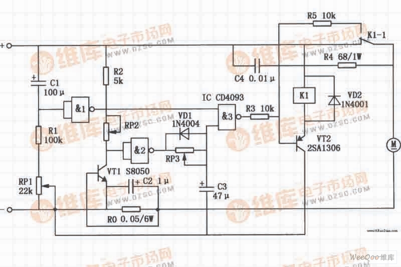
The high-power motor over-current protection circuit is shown in the figure, and Ro is the current sampling resistor. In order to prevent the circuit from malfunctioning due to the large current generated by the motor during startup, the startup protection delay circuit is composed of Cl, Rl, RPl and NAND gate 1. When the motor starts to start, there is no voltage on the Cl. At this time, the NAND gate 1 outputs a low level, and the NAND gate 3 outputs a high level, so that VT2 is in an off state, the relay Kl does not work, and its contact remains normally closed. The DC motor can be supplied with normal power. When the terminal voltage of Cl gradually rises to a certain value, NAND gate 1 is turned over, the output terminal becomes high level, and the power-on protection startup circuit ends. After that, the output state of NAND gate 3 is RP2, R2, VTl. And Ro and other components of the current detection circuit control.

High-power motor overcurrent protection circuit
SMD Piezoelectric Buzzers are generally smaller than pin type Piezoelectric Buzzers. They are optimized for small devices such as blood glucose meter, clinical/forehead thermometers, smart glasses, and portable terminals.
From product designing, purchasing and testing, every step is controlled strictly by our QC staffs in order to make sure the perfect quality of our products. Currently, over 70% products are exported to US. South East Asia and Europe.
Smd Piezo Buzzer,Piezo Passive Smd Buzzer,Portable Micro Alarm Buzzer,Passive Micro Smt Alarm Buzzer
Jiangsu Huawha Electronices Co.,Ltd , https://www.hnbuzzer.com