A remote data acquisition system was developed to solve the problem of data uploading in the remote areas of the navy. The system uses GPS (Global Positioning System) and GIS (Geographic Information System) technology to enable intelligent and standardized management.
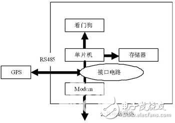
The system consists of two parts: data collection, transmission and management center. Among them, the data acquisition part mainly includes the watchdog circuit, data storage, interface and Modem (see Figure 1).

Figure 1 Remote data acquisition system structure
Application of power-down protection circuit For this system, when the power supply component is suddenly powered off or the voltage suddenly drops, the system will enter a chaotic state, and even if the voltage returns to normal, the system will not work properly. The most effective way to deal with such accidents is to increase the power-down protection system.
The power-down protection system generally consists of a low-power CMOS-RAM, a power supply circuit, and a control circuit. The power supply circuit ensures that the system supplies power to the RAM when the system is normal. When the power is off, it automatically switches to the backup battery to supply power to the RAM. The control circuit ensures that the RAM can be read and written normally when the power is supplied.
M is in a protected state. After analysis, it is found that if the system power supply changes the RAM first, and the system has not been reset, when the microprocessor is working normally, if the RAM is read and written, because it is already in the protection state, the data cannot be read. The phenomenon of not writing can cause system failure. For the problem that the microprocessor reset level and the power-down protection level are inconsistent and affect the normal operation of the system, we use a microprocessor monitoring circuit to link the system reset with the power-down protection. In this way, the memory is in a protected state when the system is reset, and the memory can be read and written normally when the system is working. The specific circuit implementation uses the microprocessor monitor MAX791.
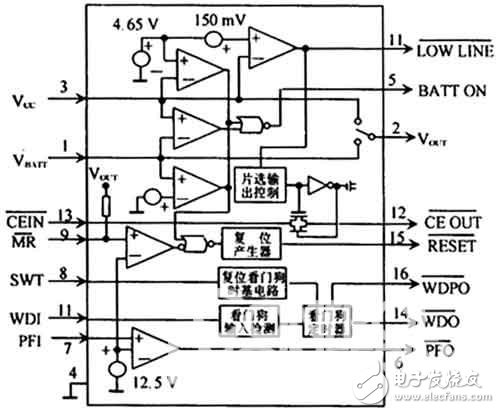
The MAX791 is a high-performance microprocessor power monitoring circuit from MAXM that is available in a 16-pin DIP package that includes microprocessor reset, battery backup, watchdog circuitry, CMOS-RAM write protection and power Alarms, etc., the logic block diagram is shown in Figure 2. In the figure, VCC and Vout are power input and output respectively, Vbatt is battery input; LOW LINE is power low output, SWT, WDI, WDO, WDP are watchdog timing setting, trigger input, timeout output and timeout pulse respectively; PFI The PFO and the PFO are the power failure input and output, respectively, and the PFO goes low when the PFI is lower than 1.25V to generate an alarm signal.

Figure 2 MAX791 logic block diagram

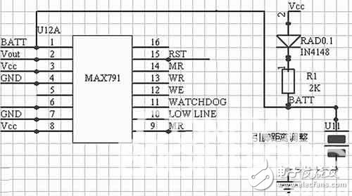
Figure 3 power-down protection circuit diagram
The following describes the high-reliability power-down protection circuit implemented by the MAX791 microprocessor monitoring circuit according to the above principle.
The RST signal of the MAX791 is connected to the memory CE. When the Vcc voltage is lower than the normal voltage, the RST output continues to be low to prevent the power supply from malfunctioning. The function of diode IN4148 is to switch Vcc and battery voltage. Under normal circumstances, Vcc charges the battery and supplies power to the entire circuit. When the power supply Vcc disappears, the power is switched to the battery, and the battery only supplies power to the memory through the MAX791.
In addition, the MAX791's power alarm feature allows the computer to record system parameters at the moment of power outage. Analysis of the circuit in Figure 2, when Vcc drops to 4.65V ± 150mV, LOWLINE produces a negative transition, sending an interrupt request to the microcontroller. Due to the energy storage effect, Vcc is reduced from 4.8V to 4.65V for several ms. Use this time to record breakpoints and real-time parameters in the interrupt service routine. After re-calling, you can transfer to the breakpoint to continue execution.
Compared with the use of other circuits to implement the watchdog function, the single-chip power-down protection system composed of the MAX791 microprocessor monitoring circuit has the advantages of stability and speed, and can effectively improve the reliability of the single-chip application system, and the practical application effect is ideal.
Stator and rotor laminations are an important part of motors and generators. For small-size and large batch laminations, we usually use the progressive punching. The advantage of progressive punching is that it can be mass-produced in a short time. But the cost of the progressive punching die is high and manufacturing period of progressive punching die is long. Usually the outer diameter is under 300mm.
Stator And Rotor Lamination By Progressive Punching,Rotor Lamination,Motor Rotor Stator,Motor Rotor
Henan Yongrong Power Technology Co., Ltd , https://www.hnyongrongglobal.com