Overview
The Wireless Charging Alliance (WPC) Qi standard implementation enables wireless charging capabilities for a variety of end applications. The size and/or power requirements of the receiver (Rx) coil for each application may vary. To achieve a successful and efficient Qi standard Rx design, the Rx coil is a key component. In addition, we still have a lot of design methods and balances to consider. Therefore, when implementing a solution, designers must carefully choose the method and design it in an orderly manner. This article will discuss in detail some of the technical issues to be solved to achieve a successful Rx coil design. The article covers the Qi standard system model of the basic transformer, Rx coil measurements and system level effects, and some methods to check if a design can run successfully. We assume that the readers of this article have mastered the basics of the Qi standard inductive power system.
Transformer Qi standard system
For many near-field wireless power systems, such as WPC-defined wireless power systems, magnetic power transfer behavior can be modeled using a simple transformer. Traditional transformers are usually a single physical structure with two windings wound around a core material and the core is much more magnetically conductive than air (Figure 1). Since conventional transformers use a highly magnetically permeable material to transmit magnetic flux, most (but not all) of the magnetic flux produced by one coil is coupled to the other. The degree of coupling can be determined by a parameter called the coupling coefficient, which is expressed in k (ranging from 0 to 1).
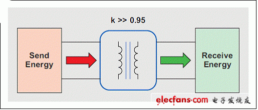
Figure 1 A traditional transformer with a physical structure
Three parameters define a two-coil transformer:
L11 is the self-inductance of coil 1.
L22 is the self-inductance of coil 2.
L12 is the mutual inductance of coils 1 and 2.
The coupling coefficient between the two coils can be expressed as: 
Then, using the coupled inductor shown in Figure 2, the ideal transformer can be modeled.
Using the voltage and current relationship of the inductor, the nodal equation of the two-coil transformer can be obtained: 

To facilitate circuit analysis, the model shown in Figure 2 can be represented by the common name of the cantilever model, as shown in Figure 3. The magnetic coupling and mutual inductance here are simplified to leakage inductance and magnetizing inductance. Thus, through a circuit implementation, we can understand the physical properties of this coupling. In the case of an ideal transformer, we can calculate its turns ratio using the following equation:
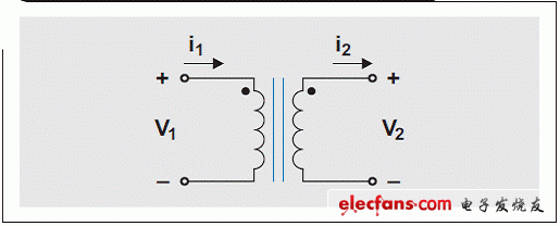
Figure 2 Ideal model of a traditional transformer 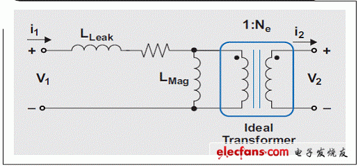
Figure 3 Cantilever model of a conventional transformer
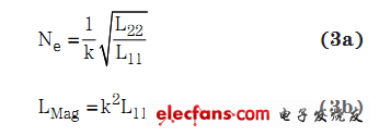
In a strongly coupled system, the leakage inductance accounts for a small percentage of the magnetizing inductance, so this parameter is negligible when an approximation is sought. In addition to high coupling, the series resonant capacitor used in the Qi standard system also reduces the effects of leakage inductance. Therefore, the approximate value of the voltage gain of the primary coil to the secondary coil is: 
The transformer of the Qi standard system consists of two separate physical devices: the transmitter (Tx) and the receiver (Rx), each with an isolated coil. When Tx and Rx are placed close together, they form a coupled inductive relationship that can be simply modeled as a two-coil transformer using an air core (see Figure 4). The shielding material at both ends acts as a magnetic flux short circuit. This allows the magnetic field lines (magnetic flux) to exist between the two coils. Figure 5 shows the 2D simulation of the magnetic field lines during a typical run.
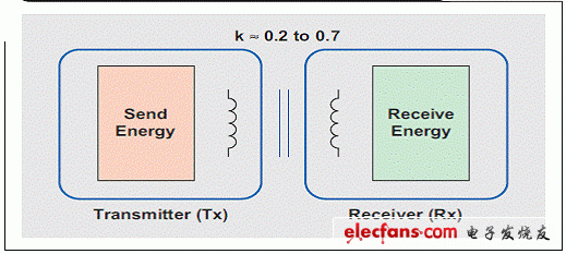
Figure 4 Simple inductive coupling transformer using an air core
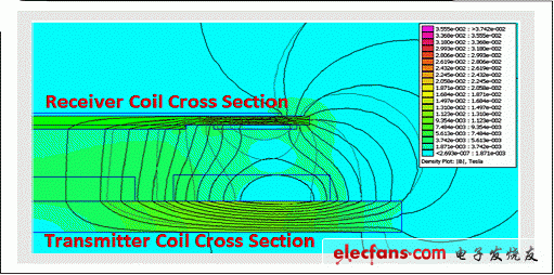
Figure 5 Example of magnetic field lines between two mutually coupled coils
In the case of a typical Qi standard system, the coupling factor (k) is much lower than in the case of a conventional transformer. Conventional transformers have coupling coefficients ranging from 0.95 to 0.99. For example, 95% to 99% of the magnetic flux is coupled to the secondary coil; however, for the Qi standard system, the coupling factor ranges from 0.2 to 0.7, which is 20% to 70%. In most cases, the Qi standard tends to use a series resonant capacitor on Tx and Rx to alleviate this low coupling problem. This capacitor compensates for the resonant leakage inductance.
Mini PC
Are you tired on big and messy wires on traditional computer tower? If yes, mini pc bring clean and space saving working environment back to you. Whatever daily tasks, like browsing web pages, documents checking or making, online teaching or learning, entertainments, etc. Or heavy duty handling, like photshops, video or music editing, gaming, apps developing, engineering drawing, designing jobs, etc. You can always find a right pc mini intel at this store.
Mini PC Office is an most and popular series designed for those who mainly run WPS, photoshops, PR, email, entertainments, etc. Sometimes, also call it as mini pc officeworks or home assistant mini pc.
Mini Gaming PC comes with higher level processors, like intel i3, i5, i7 10th, 11th or 12th; bigger memory and storage, like 16GB or 32GB ram, 512gb up to 1tb. Of course, rich slots support linking with two or more monitors or devices.
Except mini pc windows 11, there are also All In One PC , Student Laptop, Gaming Laptop , Android Tablet, Yoga Laptop , etc.
Mini PC Windows 11,High Performance Mini PC,Mini PC DDR4,PC Mini Intel
Henan Shuyi Electronics Co., Ltd. , https://www.shuyipc.com