Road and street lighting has long been the main component of outdoor lighting, especially road lighting and tunnel lighting, which has often become an indispensable part of urban reconstruction and urban development. China's road and street lighting has a long history, and there are still many exports to Europe and Southeast Asian countries. If it can be consistent with international standards, it will greatly facilitate the export and import of roads and street lamps.
At present, the current national standard for road and street lighting is GB 7000.5â€2005, which is equivalent to IEC 60598â€2â€3: 2002, and the latest IEC version is IEC 60598â€2â€3: 2002 + A1: 2011, higher than current The national standard, and our national standards will also be updated in the near future according to the latest IEC version. So understanding the latest version of the trend and the differences between the two versions will help to develop our design direction for the latest road street luminaires, and the differences between the two are mainly concentrated in the glass cover test section of the structural chapter.
First, the difference in the qualification conditions of the glass cover structure test
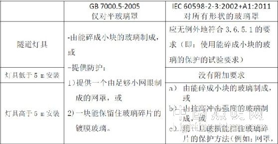
The glass cover structure test of roads and street lighting is mainly for the simulation test of the glass cover of such lamps when the glass fragments are broken due to the cracking of the glass such as stone cracks. The current national standard and the latest IEC standard have relatively large differences in terms of eligibility conditions, as shown in Table 1.
Table 1 Differences in the qualification conditions of the two versions of the glass cover


As can be seen from Table 1, the new version has the following differences with respect to the old version:
1) Expanded the scope of the test: from the original only for the flat glass cover to the glass cover for all shapes (including planes and curved surfaces);
2) According to the usage, it is classified into three types: tunnel lighting, installation height less than 5m, installation height higher than 5m, different types of requirements. When designing, different glass materials can be used according to the direction of use set by the product. When testing, it should be judged which category it belongs to;
3) For the installation height higher than 5m, in addition to the requirement of adding a curved glass cover, the qualified condition of the glass cover made of glass with impact resistance is also increased;
4) For the case of the mesh cover, the old version only said that it is made of enough small mesh, but what is small enough but not detailed, the new version clearly defines the requirements that need to be met: once the damage can block the glass fragments. That is to say, the size of the grid should match the condition of the glass used: it can meet all the requirements of the glass cover.
Second, the glass cover structure test
From Table 1, we can see that the test of the latest IEC standard mainly judges the eligibility from three aspects. Below we analyze and verify these three aspects separately.
1. For a glass cover made of glass that can be broken into small pieces
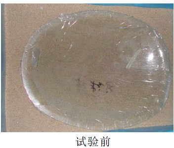
The biggest difference in this part is the increase of the test requirements for curved glass. Therefore, we use the ordinary forming glass cover for the test in this part. The so-called ordinary shaped glass cover is a glass cover formed of ordinary flat glass. There are no test method provisions in the current national standard, and the test method is specified in the latest IEC standard 3.6.5.1. Preparation before the test: For the formed glass, the glass member should be supported on all surfaces (example of the test method is that materials such as sand or soil can be used). The thickness of the material used as the support surface should be greater than 30 mm. In order to avoid any movement of the granules (sheet), the glass surface should be completely covered by a layer of adhesive film. We use sand to provide support and completely cover the glass with scotch tape, see Figure 1. For flat glass covers, this part of the preparation is the same as the current national standard.
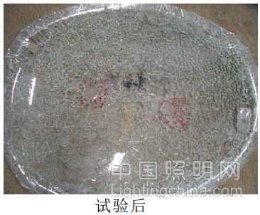
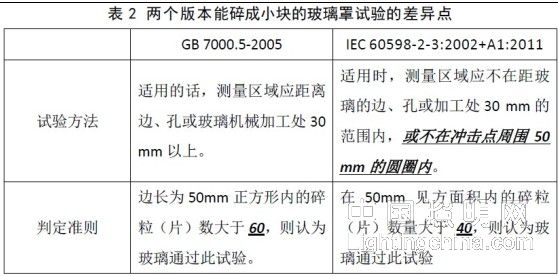
Then, use a center punch to impact the glass at the center of the glass cover (from the inner or outer surface) (we chose a surface that does not cover the scotch tape). Within 5 min of the fragmentation, within the glass boundary, estimate the number of granules (sheets) within the area of ​​50 mm square in the center of the coarsest fragmentation zone. The measurement area should not be within 30 mm of the edge, hole or machining of the glass, or within a 50 mm circle around the impact point. see picture 1.


Figure 1 Formed glass cover before and after the test
Finally, according to the standard requirement number of 50mm, the number of granules (sheets) in the product area is 81, which is greater than 40 specified in the standard. It is considered that the glass passes this test and it is verified that the forming glass cover test is qualified.
After the test, we summarized the differences between the two versions of the test method and the criteria (the bold italicized line), the same part is not listed, see Table 2.

2. For glass cover made of glass with high impact strength
This part is completely new, we have selected two 5J strength forming glass covers for verification testing. The so-called 5J strength forming glass cover is a glass cover that the glass manufacturer claims to be resistant to high impact strength of 5J. This concept is not covered in the current national standard and is the newly added assessment content in the latest IEC standard. The test method has been clarified in the same IEC standard 3.6.5.2. Since the glass cover is not installed on the luminaire, the luminaire and glass cover required by the standard should be pretreated with GB 7000.1 Clause 12.3. In progress, we just verified the test process. Two 5J-strength shaped glass covers of different sizes were selected and tested on the outer surface of the glass (opposite the light source). The test procedure was carried out in accordance with the standard GB/T 20138, and the test equipment used was a vertical drop hammer in accordance with GB/T 2423.55.
The first test: We placed the glass cover flat on the level ground, and only a newspaper was placed underneath. The weight of the vertical drop hammer was 1.7kg. The height of the contact point of the drop hammer to the glass cover was 300 mm, and after the test, the glass cover was broken.
We were a bit surprised by the results, because the glass manufacturer said that although it is a glass cover that claims 5J, it should be able to withstand 7J of energy. Then look back at the standard requirements: the test should be performed on a sample and on the outer surface of the glass (opposite the light source) mounted on the luminaire. We think that although the glass cover cannot be installed on the luminaire at present, it should be simulated as much as possible. The actual road and street luminaires are usually made of outdoor luminaires, and rubber seals are usually used to ensure the IP rating. So we will use the glass. The cover is placed on the rubber mat on the level ground for a second test. After the test, the glass cover is in good condition and meets the requirements that the glass should not be broken after impact in the standard.

Then, according to the test method of the ordinary shaped glass cover, it is obvious that the number of broken pieces (sheets) after the chipping is significantly larger than the standard 20. The case of the glass cover before and after the test is shown in Figure 2 and Figure 3. Both glass covers pass this test. It has been verified that the two 5J strength forming glass covers passed the test.
This verification test concluded that the decisive factor of the 5J impact energy test is not only the material of the glass itself, but also related to the actual installation and location of the glass cover. In the test, when not placed on the rubber mat, the glass cover did not move and directly ruptured; when placed on the rubber mat, the glass cover had a slight jump after the impact, indicating that the rubber mat provided a buffer and removed some of the energy. For the glass cover directly mounted on the luminaire, in addition to the rubber sealing ring, the fixing clip and fixing method should also disperse a part of the energy, and the test effect may be better. Therefore, considering the design of the luminaire from the three aspects of the glass material, the seal material and the glass cover fixing method, it is not difficult to pass the test.
3. For the protection method that can block the glass fragments once damaged (for example: mesh cover, film cover)
In addition to the above-mentioned requirements that need to be met, the test methods are unchanged and are visually inspected, but the luminaire manufacturer should provide the laboratory with a statement of the method of protection used. In order to verify the effectiveness of the protection method adopted, we also selected a coated glass for the test, and also tested the impact glass by the flat glass cover test method.

After the test, we erected the glass cover to observe the effectiveness of the film. The glass before and after the test and the erected glass are shown in Fig. 4.
After the verification test, the flat glass cover of the film can block the glass fragments after the damage, and the film is effective and meets the standard requirements.
In addition, for the use of the grid form, it has not been considered feasible before, because the grid is too dense, it will affect the light transmission and internal heat dissipation of the lamp, and the mesh is too sparse to ensure that all the particles can be blocked. . However, in the usual inspection, it was found that the glass cover made of special material, after the impact test, the glass cover does not break into large and small pieces (granules) like ordinary glass, without irregularity, but only broken into Two or three relatively large glass will not produce small glass, and the fracture surface has no sharp angle. The mesh used is not very dense, but it can definitely block it. It can be seen that as long as the glass material and the mesh size are well matched, it is not impossible to use the net cover protection method.
The above is the verification and analysis of the glass cover structure test part of the latest IEC standard for road and street lighting, and the main difference from the current national standard. I hope to be helpful in the design, manufacture and inspection of this part of the future.
Edit: Nizi
Braided sleeves are widely used in computer power cord, audio-video, automotive, aviation, wire and cable industries. It has protect and beautify the role. Its unique mesh characteristics but also has good ventilation, and a thermal diffusion function in a timely manner.Wrap wires, protect the wires from erosion and moisture. And beautify the wires.
Electrical Cable Braided Sleeving,Sleeves For Car Cables,Expandable Sleeve For Cables,Cabel Sleeve For Wire Harness
Shenzhen Huiyunhai Tech.Co.,Ltd , https://www.hyhbraidedsleeve.com