In the hot download of the "Green Lighting Technology Special Issue" in May, how can you miss it!
As a light source, dimming is very important. Not only to get a more comfortable environment in the home, today, the purpose of reducing unnecessary electric light to further achieve energy saving and emission reduction is even more important. Moreover, for LED light sources, dimming is easier to implement than other fluorescent lamps, energy-saving lamps, high-pressure sodium lamps, etc., so it is necessary to add dimming function to various types of LED lamps.
The first part adopts the dimming technology of DC power LED
One. Adjust the brightness by adjusting the forward current
To change the brightness of the LED is very easy to achieve. The first thing that comes to mind is to change its drive current because the brightness of the LED is almost directly proportional to its drive current. Figure 1 shows the relative intensity and forward current of Cree's XLampXP-G output.
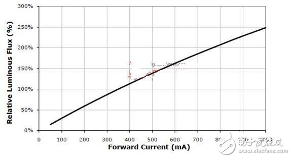
Figure 1. The relationship between the relative intensity and forward current of the XLampXP-G output.
As can be seen from the figure, if the light output at 350 mA is taken as 100%, the light output at 200 mA is about 60%, and at 100 mA is about 25%. Therefore, the adjustment of the brightness can be easily achieved by adjusting the current.
1.1 Method of adjusting forward current
The easiest way to adjust the LED current is to change the current sense resistor in series with the LED load (Figure 2a). Almost all DC-DC constant current chips have an interface for detecting current, which is the detected voltage and the internal reference voltage of the chip. Compare to control the constant current. However, the value of this sense resistor is usually very small, only a few ohms. If you want to install a potentiometer of zero ohms on the wall to adjust the current is not possible, because the lead resistance will also have a few ohms. Therefore, some chips provide a control voltage interface, and the output constant voltage can be changed by changing the input control voltage. For example, Linear Technology's LT3478 (Fig. 2b) can change the constant current value of its output as long as the ratio of R1 and R2 is changed.
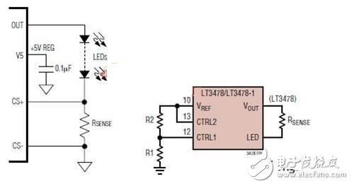
Figure 2 output constant current value adjustment
1.2 Adjusting the forward current will cause the chromatogram to shift
However, adjusting the brightness by adjusting the forward current has a problem, that is, it also changes its spectral and color temperature while adjusting the brightness. Because white LEDs are currently generated by blue LEDs to excite phosphors, when the forward current is reduced, the brightness of the blue LEDs increases and the thickness of the phosphors is not scaled down, thereby increasing the dominant wavelength of the spectrum. A specific example is shown in Figure 3.
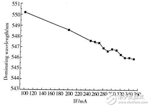
Figure 3 shows the relationship between dominant wavelength and forward current
When the forward current is 350 mA, the dominant wavelength is 545.8 nm; when the forward current is reduced to 200 mA, the dominant wavelength is 548.6 nm; when the forward current is reduced to 100 mA, the dominant wavelength is 550.2 nm.
A change in forward current also causes a change in color temperature (Figure 4).
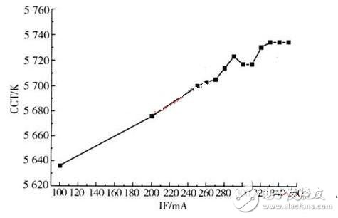
Figure 4. Relationship between color temperature and forward current of white LEDs
As can be seen from Fig. 4, when the forward current is 350 mA, the color temperature is 5734K, and when the forward current is increased to 350 mA, the color temperature is shifted to 5636K. When the current is further reduced, the color temperature changes to a warm color.
Of course, these problems may not be a big problem in general actual lighting. However, in the RGB LED system, color shift is caused, and the human eye is very sensitive to color deviation, and therefore is not allowed.
1.3 Adjusting the current will cause serious problems that make the constant current source unable to work.
However, in the specific implementation, dimming by using the forward current method may cause a more serious problem.
We know that LEDs are usually driven by DC-DC constant current drive power, which is usually divided into boost or buck (of course, buck-boost, but due to low efficiency , the price is expensive and not commonly used). Whether the boost type or the step-down type is used is determined by the relationship between the power supply voltage and the LED load voltage. If the power supply voltage is lower than the load voltage, the boost type is used; if the power supply voltage is higher than the load voltage, the step-down type is used. The forward voltage of the LED is determined by its forward current. From the volt-ampere characteristics of the LED (Fig. 5), it can be seen that the change in the forward current causes a corresponding change in the forward voltage. Specifically, the decrease in the forward current also causes a decrease in the forward voltage. Therefore, when the current is turned down, the forward voltage of the LED is also reduced. This will change the relationship between the supply voltage and the load voltage.
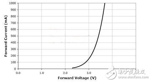
Figure 5 volt-ampere characteristics of LED
For example, in an LED luminaire with an input of 24V, eight 1W high-power LEDs are connected in series. At a forward current of 350 mA, the forward voltage of each LED is 3.3V. Then 8 series is 2*V, which is higher than the input voltage. Therefore, a boost type constant current source should be used. However, in order to dim, the current is reduced to 100 mA. At this time, the forward voltage is only 2.8 V, and 8 in series is 22.4 V, and the load voltage becomes lower than the power supply voltage. This step-up constant current source does not work at all, but should be a step-down type. For a boost type constant current source, it must not work for buck, and finally the LED will flicker. In fact, as long as a boost-type constant current source is used, when dimming with a forward current is regulated, it is almost always caused to flicker as long as the brightness is adjusted to a very low level. Because the LED load voltage at that time must be lower than the supply voltage. Many people do not understand the problems, but also always go to the dimming circuit to find the problem, it is useless.
There is less problem with the buck constant current source, because if the original supply voltage is higher than the load voltage, when the brightness is low, the load voltage is reduced, so a buck constant current source is still needed. However, if the very low forward current is adjusted, the load voltage of the LED becomes very low. At that time, the step-down ratio is very large, and it may exceed the normal working range of the buck constant current source, and it will also make it Can't work and produce flicker.
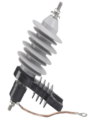
The Lightning Surge Arrester is designed for trouble-free power distribution. Polymer Surge Arrester protect transformers, switchgear and other equipment from switching and lightning surges. Polymer specis lighting arrester meet or exceed all requirements of the latest IEC standards and can be selected to match the range of pollution and energy requirements. Polymer Lightning Arrester should be installed in parallel between the line and ground to the transformer or cable termination or other object to be protected. Compared with arresters made of ceramic materials, polymer lightning protection devices can be widely used in medium and high voltage power grids in coastal and heavily polluted areas.
Features
1. Small volume and light weight2. Protecting the shell body from breaking up when the pressure from thermal shock released
3. Easy to tell if the application still work due to its carbonization when shell body flashs over
4. Better performance in high contamination areas
5. Good sealing performance
| MAIN DIMENSIONS AND STANDARD PARTICULARS | |||
| Type | YH10W-11KV | YH10W-24KV | YH10W-33KV |
| Rated Voltage,KV | 11 | 24 | 33 |
| Norminal Discharge Current,KA | 10 | 10 | 10 |
| Max Continuous Operating Voltage,KA | 9.3 | 19.5 | 26.8 |
| Residual Voltage Steep current,KV | 38 | 76 | 104.5 |
| Residual Voltage Switching Surge,KV | 30.8 | 61.6 | 84.7 |
| Residual Voltage Lightning Impulse,KV | 33 | 72 | 99 |
| 4/10μs high current impulse,KA | 100 | 100 | 100 |
| Creepage Distance,MM | 340 | 750 | 900 |
| Weight,KG | 1.62 | 3 | 3.05 |
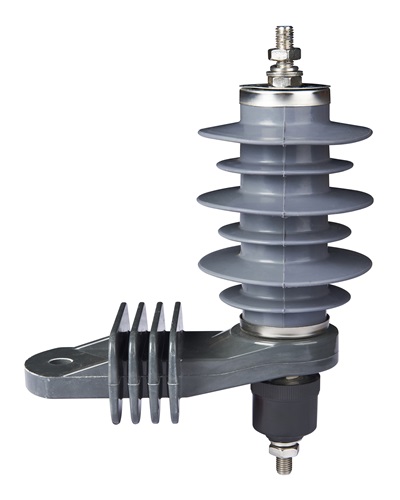
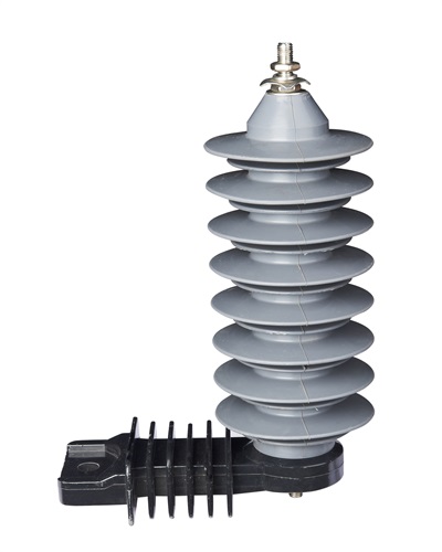
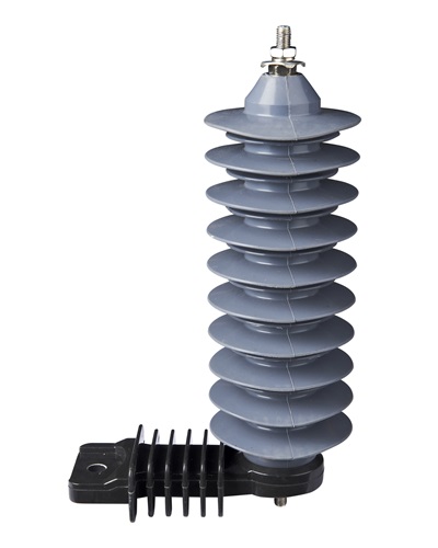
We warmly welcome friends both domestic and abroad to visit our company, if you have any questions, please contact with us directly.
Lightning Surge Arrester,Polymer Surge Arrester,Polymer Specis Lighting Arrester,Polymer Lightning Arrester
FUZHOU SINGREE IMP.& EXP.CO.,LTD. , https://www.cninsulators.com