The source of electromagnetic interference generated by automobiles is not simply an ignition system. Electromagnetic interference is also generated by various electronic and electrical equipment used in vehicles. Interference not only affects the radio equipment outside the vehicle, but also adversely affects various electronic components inside the vehicle.
1. Electromagnetic interference in automobiles
Electromagnetic interference generated by automobiles can cause interactions inside the car, for example as follows:
Example 1, a medium-to-high-end sedan with a high-performance ABS system. The prototype encountered a rainy day in a live test and started the wiper. At a certain speed, the ABS suddenly lost its effect.
Example 2: A certain type of domestically produced micro-car, its generator regulator often appears to be easily damaged by breakdown. After investigation, when the wiper works, this damage phenomenon is easy to occur. The main reason for this phenomenon is that the wiper drive motor is an inductive load. When the power is cut off, reverse current is generated and transmitted to the power supply system through the power line, thereby generating interference pulses in the power system, so that some electronic components cannot work normally. And even damaged.
Example 3: An airbag developed and produced in China suddenly detonated on the assembly line of a vehicle. It was found that the electronic detonation controller of the airbag cannot withstand the strong environmental radiation electromagnetic field, and when there is electrostatic discharge, it may malfunction.
1) Characteristics of electromagnetic interference in automobiles
The characteristics of the electromagnetic interference inside the vehicle are different from the interference of the vehicle to the outside. In-vehicle electromagnetic interference can be transmitted through various connection cables, and it can also be transmitted by means of coupling and space-assisted emission. Typical forms are: conduction interference along the power line; interference from human body electrostatic discharge to electronic components; interference energy through space radiation. The following is an analysis of the characteristics of some typical sources of interference.
2) The engine ignition system produces interference that is conducted along the power line
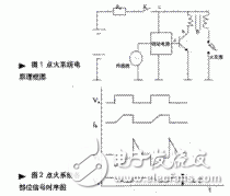
The circuit block diagram of the engine ignition system is shown in Figure 1. The sensor obtains the ignition signal Va, and the driving circuit generates an on-off pulse current Ib at the primary of the ignition coil, and the coil secondary generates a high-voltage pulse to discharge the spark plug to ignite the engine fuel mixture for work. When the primary loop of the coil changes, the primary winding generates a transient voltage, the secondary winding generates a high voltage to discharge the spark plug, and the residual energy forms high-frequency electromagnetic radiation into the space. The transient voltage in the primary loop is transmitted along the power line to the power system, interfering with the power system, producing a ripple voltage ΔV. As shown in Figure 2. Generally, the experimental results show that ΔV is 2 to 4V.

Various electronic control units used in automobiles require a stable power supply voltage for proper operation. When a voltage fluctuation (such as ΔV) occurs in the power supply system, it will affect the normal operation of the electronic module.
3) Inductive load produces interference conducted along the power line

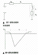
Various types of motors used in automobiles are inductive loads. Such as: wiper drive motor; car starter motor; heater motor. This type of load characteristic circuit is shown in Figure 3. When the power supply to the inductive load is suddenly cut off, a reverse transient voltage Vc is generated, as shown in FIG. The larger the initial energy storage of the coil, the faster the turn-off speed and the higher the transient overvoltage. The measured results show that Va is generally -100V to 300V; is is 0.2s to 0.5s.
Although this type of interference is not continuous, its transient voltage amplitude is quite large, and occasional occurrences can seriously affect or even damage electronic modules. The generator regulator breakdown damage described in the previous section is a serious consequence of this reverse transient voltage.
5. Interference of electrostatic discharge on electronic components in the car
The human body generates static electricity, especially in the northern part of China. The winter climate is dry and the human body is prone to static electricity. The human body static electricity will be released when it encounters some conductors. There is direct discharge, which people can't feel. When the static electricity is stored to a certain extent, it will be discharged through the air, and even a spark will be generated, and people will have a strong discharge feeling. This type of electrostatic discharge is inevitable when people use a car.
2. EMI hazards and characteristics of automotive electronics
Industrial development not only brings to the living environment some tangible pollution that can be recognized by the senses, such as water, air and noise pollution. However, with the development of electronic technology, especially the popularization of digital circuits, mobile communications and switching power supplies, there is an invisible pollution that cannot be felt by the senses. This is electromagnetic interference (EMI), or electromagnetic noise.
The electromagnetic waves radiated and leaked by electronic equipment not only cause serious interference to the electronic equipment itself, but also threaten the health and safety of human beings.
The various appliances on modern cars work differently, and they invade each other in different ways. Generally, all automotive electrical appliances are compatible, that is, they can work together in the vehicle without disturbing the normal operation of other electrical appliances, and also have the ability to resist interference from other electrical appliances.
For the circuit of automotive electronic equipment, the oscillations in the circuit excited by any factor will be transmitted in the form of electromagnetic waves through wires, etc., not only interfere with the radio, communication equipment, but also the electronic system with high-frequency response characteristics on the vehicle. It will generate electromagnetic interference. At the same time, radio waves, radio, radio stations, etc., which are used by external transceivers, emit radio waves, which can interfere with the instruments on the car and cause the electronic control device to lose control. Therefore, the application computer (controller) on the car should have good electromagnetic shielding measures. Once the shielding is damaged, it will cause abnormal work.
Characteristics of electromagnetic interference propagation in the car:
(1) An inductive load produces interference that is conducted along the power line. Various inductive loads used in automobiles, such as wiper drive motors, car starters, and heater motors. When the power supply is suddenly cut off, the reverse transient voltage U c is generated. The larger the initial energy storage of the coil, the faster the shutdown speed, and the higher the transient overvoltage. Generally, U c is a 100~300V; ts is 0.2~0.5s. Although this kind of disturbance does not have continuity, its transient voltage amplitude is quite large, which will seriously affect or even damage the electronic module. Generator regulator breakdown damage is a serious consequence of this reverse transient voltage.
(2) Electrostatic discharge interferes with electronic components in the vehicle. When the conductor is encountered, it will be released. When the static electricity is stored to a certain extent, it will be discharged through the air, and even sparks will occur. People will have a strong discharge feeling. When using a car, this electrostatic discharge phenomenon will inevitably cause electrostatic discharge interference. Voltage, short time, small current. The degree of interference is huge, which may cause some electronic control units to malfunction, which will seriously damage the electronic unit.
(3) Mutual coupling interference between components or cables. In the car, various cables are often bundled into a bundle along the inner side of the car. Transient interference in the power line can be plagued into the signal line or the control line to form a differential mode signal, which will affect the electronic modules such as the ECU in the car.
(4) Radiation interference. The form of electromagnetic wave radiation that interferes with energy, and the frequency range is from 150 kHz to 1000 MHz. The EMI interference sources of automotive electronic equipment are: 1 ignition system, the ten disturbances appear as rhythmic pops or ticks in the receiver audio, and the pitch is directly related to the engine speed, and the interference amplitude increases when the engine load increases. Big. A common solution to ignition noise is to install a resistor spark plug and wire. Currently, most cars come standard with resistor spark plugs and wires. Frequent replacement of new spark plugs and wires will help reduce noise because much of the noise is due to ignition system component failure. 2 charging system, including alternator, controlled by a solid state regulator. Since the alternating current is only rectified in the alternator and is not filtered, there is ripple in the output. Charging system noise is transmitted to the device through the car wiring, affecting the audio portion of the receiver and transmitter. This noise can be discerned from the receiver's audio or the click in the transmitted signal. A more accurate method is to temporarily disconnect the charging system. The pitch and intensity of the charging system noise are related to engine speed and charging system load. When the charge of the charging system increases when the light is turned on, it can be found that the click is louder. At this time, check whether the connection between the alternator and the battery is corroded or poorly contacted, and if the solid-state voltage regulator is good or not, use a 0.47μF and 0.01μF capacitor in parallel to connect the output to the ground for filtering.
Since the car uses a plurality of different motors, these motors are likely to generate EMI, and it is difficult to determine which problem is caused by the disturbance sound. It is generally buzzing and has a buzzing sound similar to a charging system. The diagnosis of motor disturbances is aided by special instruments. Interference can not only be conducted but also radiated, so it is necessary to filter near the source of interference.
The microprocessor (microcontroller) used in the car needs to be driven by a clock. The clock generation circuit is an oscillating circuit. Since the oscillating waveform is a square wave, its harmonic frequency is rich and can be extended to a very high frequency, so the receiver is likely to be affected by the interference signal of equal frequency interval, or can be heard throughout the band. Broadband digital noise. You can use the receiver to adjust the interference frequency to detect which board has a problem, and then reduce the interference by adding a shield or properly grounding the shield. In addition, putting a magnetic ring on the wire can also help reduce interference. . The electronic equipment of a car affects the radio equipment, which also affects the electronic equipment of the car. Make sure that the power cord, antenna feeder and car wiring and electronic system are as far as possible. Install the antenna correctly, preferably on the roof or at the back of the car. Try to minimize the standing wave ratio (SWR) of the large line system. Check if the antenna feeder shield is good and the shield is dense enough.
3. Classification and causes of radio interference
Radio interference means that in the radio frequency (9 kHz to 3000 GHz) frequency band, radio interference is classified into natural disturbance (from natural phenomena and uncontrollable) according to the nature of the interference source and human interference (from the machine or other people, it is ok controlling). Human interference can be divided into two types: radio interference and non-radio interference.
Non-radio equipment interference includes industrial, scientific research, medical and other electrical equipment interference, power line interference and other radio equipment interference mainly include:
(1) Co-channel interference. Any interference sent by other sources, which has the same frequency as a used signal and enters the receiver's intermediate frequency band in the same way, is called co-channel interference. When the carrier frequency difference occurs between the two signals, the beat interference is caused; when the modulation degree of the two signals is not large or there is a phase difference, the distortion interference is also caused. The larger the interference signal, the smaller the output signal-to-noise ratio of the receiver. When the interference signal is large enough, it can cause the receiver to block. This interference is mostly caused by the fact that the same frequency reuse distance is too small.
(2) Frequency interference. Any interference caused by the signal falling into the intermediate frequency passband after being converted into the RF passband of the receiver or the passband is called adjacent channel interference. This kind of interference will reduce the signal-to-noise ratio of the receiver and reduce the sensitivity; the strong interference signal can cause the receiver to block interference. Most of this interference is caused by the fact that the technical specifications of the radio equipment do not meet the national standards.
(3) Out-of-band interference. The interference generated by the spurious emission of the transmitter and the spurious response of the receiver is called out-of-band interference.
1 The spurious radiation interference of the transmitter. In the low frequency bands of VHF and UHF, mobile communication devices, especially those of base stations, mostly use crystal oscillators to obtain higher frequency stability. This kind of interference is usually caused by excessive frequency multiplication, poor selectivity of the frequency multiplier output loop, poor shielding isolation between the frequency multipliers, etc., which cause the spurious radiation value of the transmitter to be too large.
2 The spurious response of the receiver. The receiver not only receives useful signals, but also receives unwanted signals. The "response" capability of unwanted signals, commonly referred to as spurious response, is usually due to the spurious emissions of the transmitter and is directly related to the receiver's own local frequency purity input loop and high-level loop selectivity. .
4. Measures to reduce vehicle interference with radio
The interference of the car to the radio receiver is most severe in the ignition system, and the radius of the disturbance can reach several hundred meters. The suppression of electromagnetic interference should adopt different suppression methods according to the characteristics of different interference sources. Secondly, the way to consider the interference propagation path is: through the cable, antenna or various wires of the power supply system, electromagnetic waves can be directly radiated through coupling and space. Interference suppression should consider cost. The general processing method is to limit the interference noise generated by the interference source to a specified reasonable range; at the same time, the interfered body should have a certain ability to resist interference, so as to achieve a state of mutual coexistence and no influence.
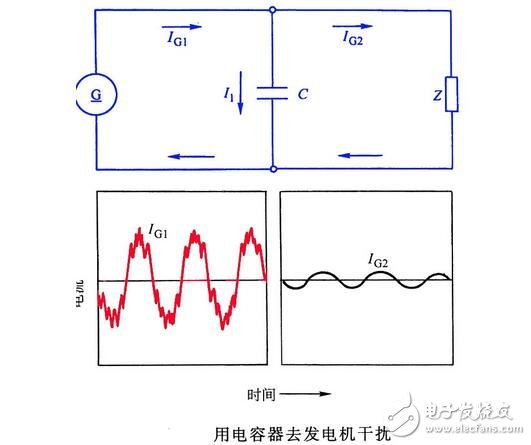
A simple and effective way to interfere with in-vehicle power systems is to use the battery as a very low-impedance, high-capacity transient voltage suppressor that absorbs the interference energy generated by various transient voltages. The battery cable should be well wired. If the negative pole is grounded, ensure that the grounding resistance is the smallest. As far as possible, the line resistance R0 should be kept to a minimum or even zero. For the interference caused by the coupling between cables, the best way is to separate the ECU control line or signal line from the power line to reduce the interference signal interference caused by the coupling. In addition, the use of shielded cable is also a good way to avoid external electromagnetic interference into the control line and signal line. For interference caused by inductive loads, the suppression can be done by paralleling a capacitor of appropriate value to eliminate reverse overvoltage.
The reason for the interference is that the self-inductance and capacitance of the wires, coils and other parts of the electrical equipment system form an oscillating circuit. When discharging in the form of a spark, high-frequency oscillation is generated, and electromagnetic waves are transmitted to the air by high-voltage wires (or wires), and cutting is received. The antenna of the machine causes interference. Modern vehicles use the following methods to prevent such interference:
(1) Add a snubber resistor. In the circuit for forming high-frequency oscillation, for example, in the high-voltage circuit between the distributor to the ignition coil and the distributor to the spark plug, the 1600~15000Ω snubber resistance is connected in series, because the resistance of the oscillating circuit is large enough to make it not See the structure of the oscillating discharge phenomenon, the electromagnetic wave no longer occurs and the radio damper resistance is disturbed.
(2) Add a snubber capacitor. Between all the contact points where spark discharge may occur, a capacitor with a capacity of 0.5~0.1μF is connected in parallel to absorb the spark and avoid the reflection of the high-frequency oscillating electromagnetic wave, so that the oscillation discharge phenomenon does not occur.

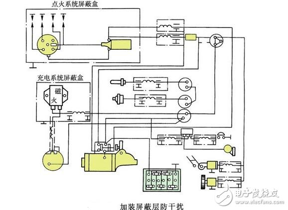
(3) Install metal shield. All electrical appliances and conductors that are susceptible to electromagnetic waves are wrapped in metal mesh or shields. In this way, when the electromagnetic wave or the high-frequency electromagnetic oscillation encounters the metal screen wall, the electromagnetic induction generates eddy current in the metal screen wall, so that the electromagnetic wave is consumed in the thermal effect of the eddy current, and cannot be emitted outward, thereby avoiding interference to radio waves. However, to avoid interference well, it is necessary to cover up completely, prevent leakage, and make the joints in good contact with the frame. In addition, the copper wire braid of the engine body can be reliably connected to the metal part of the cab, and can also be used as a metal shield. In order to prevent interference, the above methods can also be combined. For anti-jamming devices with high-sensitivity radios, see the car anti-interference system with radios.

Anti-jamming device with high-sensitivity radio equipment
5. Examples of car failure caused by electromagnetic interference
In the automotive electronic control system, the weak electrical signal generated by the sensor below 1V is susceptible to electromagnetic interference and becomes an error signal, so shielded wires are added to prevent electromagnetic interference. Once the shielded cable is damaged, the ECU will receive the disturbed signal and lose normal control, and the alarm light of the self-diagnostic system will flash.
Example 1 A Chevrolet sedan has a tweeter installed near the oxygen sensor. The power cord is taken from the ignition switch. It is found that the alarm light of the engine is alarming from time to time. The fault code is 13 (oxygen sensor) and the oxygen is measured. The output voltage of the sensor changes continuously between 0.1 and 0.3V, indicating that the oxygen sensor is normal, but when the horn is pressed, the output signal of the oxygen sensor is disordered, and the engine is also erratic. After removing the horn, troubleshoot. This is a typical example of artificially creating interference sources. There are certain design requirements for the installation position and circuit layout of automotive electrical components. Any installation of alarm and anti-theft devices will cause the electronic control system to work abnormally.
Example 2 A Toyota Crown 3.01 sedan has been driven for 120,000 km. After overhauling the engine, it only runs for a few minutes and the alarm light is alarmed. The fault code read is 55 (ie, the explosion-proof sensor is faulty), and then the code is activated. The engine is still faulty. Measuring the working voltage of the explosion-proof fuel sensor, the normal pulsating voltage below 0.5V, indicating that the explosion-proof fuel sensor is working normally. When the line is tested, it is found that the shielded wire is broken, the shielded wire is connected, and the engine is restarted after the code is broken. exclude.
The control system failure caused by electromagnetic interference mainly occurs during the engine running process. Once the engine stops running, the fault phenomenon disappears by itself. When the fault self-diagnosis system alarms, if the fault code is checked, it can be successfully realized due to the memory function of the ECU. If the fault of the control system is caused by electromagnetic interference, the voltage signal of the static measuring component will find that the sensor, circuit, ECU, etc. are all normal.
Example 3 A Toyota Camry sedan, driving tens of thousands of kilometers, ABS fault self-diagnosis system alarm, check the fault code is 31 (front right wheel speed sensor), 32 (front left wheel speed sensor), 33 (rear wheel speed sensor) 34 (rear left wheel speed sensor), considering that the four wheel speed sensors and related lines are less likely to be damaged at the same time, because the other control systems of the whole vehicle work normally, the possibility of ECU failure is small, and finally the fault will be The reason is mainly focused on electromagnetic interference. After searching, the shield line of the wheel speed sensor is seriously damaged. After the repair, clear the fault code, the road test is all normal. Originally, because the ABS sensor of the car is electromagnetic, the signal voltage generated when working in the low speed zone is extremely weak, and ABS needs to use the highly sensitive signal voltage to adjust the braking force of the wheel through the ECU. In order to ensure the accuracy of the signal, the wheel speed sensor is provided with a shielding net. Once the shielding net is damaged, the high-frequency electromagnetic wave on the car will interfere with the normal operation of the wheel speed sensor, causing the ABS to malfunction or malfunction. Self-diagnosis.
Underground Steel Tape Armoured Electrical Wire
Standard: IEC 60502 BS 6346 BS 5467
Rated Voltage: 0.6/1kV
Conductors: Class 2 stranded plain copper / aluminum as per IEC 60228
Insulation: PVC, XLPE
Bedding: PVC
Armour: Multi-Core: STA (Steel Tape Armour)
Sheath/Jacket: PVC (Polyvinyl-Chloride)
Certificates: Third party test reports
Others: Fire Cable and other property Low Voltage Power Cable can be available
Applications: Armored Cable for power networks, industrial plants, switch-boards, underground and in cable ducting where better mechanical protection is required.
Sta Power Cable,Steel Tape Armoured, Steel Tape Armored, underground cable, armoured cable
Shenzhen Bendakang Cables Holding Co., Ltd , https://www.bdkcables.com