The leakage switch tester commonly used by electricians in work is generally hand-held, small in size, light in weight, easy to carry, and can test various types of leakage protectors. It is the best test instrument for on-site or indoor detection of various leakage protectors. The general advanced tester, the test results, can be directly displayed on the instrument in digital form. It is an indispensable instrument for industrial plants and one of the instruments that the electrician is always equipped with.
Leakage switch tester is a circuit test instrument made of integrated circuit, which is mainly used to measure the operating current, breaking time, AC voltage, etc. of the leakage protector.
Proper use of various instruments will help us work, so how to use the leakage protection tester? Let's take a look at the diagram of the leakage switch tester, and then introduce the detailed use of the main functions of the leakage switch tester.
Leakage switch tester diagram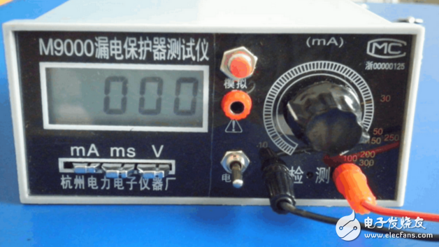
Leakage protector, commonly known as a leakage switch, is a protective device used to prevent personal electric shock and electrical fire when a circuit or electrical insulation is damaged. The leakage protector tester is mainly used to test the leakage current of the leakage protector, the leakage current and the leakage operation time. Single-phase, three-phase leakage protectors can be tested.
We use the M9000 leakage protector tester as an example. The M9000 tester does not require an additional power supply. It can work continuously for more than 200 hours using only a 9V laminated battery. The instrument is equipped with a package and a work bag that can be carried for testing.
The main technical performance of the leakage switch tester:
1. Display: three and a half LCD digital display; automatic temporary storage, lock, zero reset, overflow, battery replacement indication and fuse blow indication.
2. AC leakage current measurement: range: 0-500mA (with 500mA fuse). Accuracy level: 1.0, resolution: 1 mA.
3. Adjustable AC leakage current measurement:
Range: B type 5-100, 100-200mA.
Type C 5-100, 100-200200-300 mA.
4. AC voltage measurement: Range: 0-450V.
Accuracy level: 1.5, resolution: 1V
5. Breaking time measurement: Range: 5 - 1000ms.
Error: ±10%, resolution: 1mS.
6. Power supply:
DC9V±1V, power consumption: less than 20mw.
7. Conditions of use:
1 Temperature: working range 0-40 ° C, limit conditions, -10-50 ° C.
2 Humidity: Working range 30 ° C (20-75)% RH.
3 frequency: working range: 50±2.5HZ.
4 Altitude: no more than 2000m.
5 When using, avoid external strong electric and magnetic fields, and avoid harmful environment such as direct sunlight and corrosive gases.
8. Size: 165 & TImes; 120 & TImes; 60mm
9. Weight: about 0.5KG.
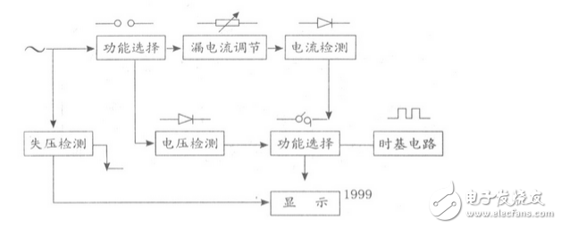
Block diagram of the leakage switch tester 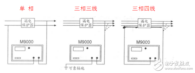
Leakage switch tester wiring diagram
The illustration shows a switch-type protector. When the combined protector is not loaded, a test line is required to pass through the transformer of the protector; when the load line is used, the test line does not pass through the transformer.
When carrying the load test, another wiring method can be adopted: one test line is connected to one phase line in the load line after the protector; the other test type line is directly connected to the ground line (body).
How to use the leakage protection tester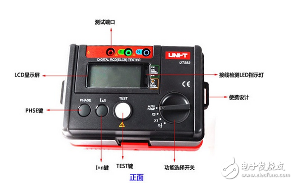
1. Before the test preparation Before the tester is connected to the power supply, the “power switch†of the instrument should be in the disconnected position. The power supply should be connected to the power supply side of the leakage protector (AC220V). The phase and neutral wires cannot be connected incorrectly. The test line passes through zero. The sequence transformer is connected to the phase line of the tester power supply. The function switch of the tester is placed in the “pre-position†position. After checking the wiring is correct, turn the “current adjustment†potentiometer on the tester panel counterclockwise to zero position, and press the “power switchâ€. At this time, mA The table and millisecond table indications should be zero. If not, press the “Reset†button.
2. Leakage protector itself leakage current or leakage current measurement (load side lead should be disassembled) The on-board function switch is placed in the "pre-position" position, after the leakage protector is put in, press the test button at this time, clockwise Slowly adjust the "current adjustment" potentiometer on the tester panel. The milliampere meter of the tester should have a milliampere value display, and the current will gradually increase until the leakage protector is activated. At this time, the reading displayed by the milliampere meter is Leakage current. The leakage current does not measure the current. The method of adjusting the current is the same as above. When the current value reaches the specified value, press the “Reset†button, the current returns to zero, and then press the “Test†button. The leakage protector does not operate, which is qualified.
3. Leakage action time measurement (load side lead should be disassembled) Before setting the leakage current value of the measurement operation time, the test line should be tested from the leakage switch load to the in-phase main contact power supply side, and the function switch is set at the “pre-position†position. After pressing the “Test†button, turn the “Current Regulation†potentiometer clockwise to adjust the current. After reaching the specified value and keeping it, disconnect the tester power switch and change the test line to the leakage switch and the detector power supply phase. The main contact load side (cannot be connected incorrectly), turn the function switch to the "test" position, close the leakage protector switch, and press the tester "power switch" (if the table indication is not zero, click "reset" The button can be used. At this time, press the “Test†button, the leakage protector should be tripped, and the millisecond meter display value is the action time under the leakage current value. If you press the “Reset†button to clear it, the above time measurement can be repeated by reclosing the leakage switch.
4. The value of the leakage current measured with the load is not the characteristic of the leakage protector, and there is generally leakage current in the load. The magnitude of the leakage current of the three-phase leakage protector with load measurement reflects the degree of three-phase leakage imbalance in the load. The measurement method is to connect the tester power supply and test line to the power supply side of each phase at the same time, and measure it by the above two methods. Be careful, you can't use three three wiring methods, otherwise the tester will burn out.
Leakage protection tester method for measuring leakage current of equipment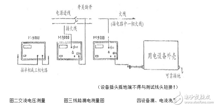
1. Press the “mA†(mA is current symbol) straight-line switch of the leakage switch tester; then turn on the power switch of the leakage switch tester.
2. First ground the electrical equipment casing, and then connect the power cord of the electrical equipment to the red socket marked “Detection†in the panel of the leakage switch tester, and at the same time, the socket with the red label and the power supply circuit in the panel of the leakage switch tester. When it is turned on, the leakage current value will be displayed on the device display.
3. After the test is completed, remove the line and turn off the power switch.
Method for measuring AC voltage by leakage protection tester1. Press the “V†(V symbol represents the voltage) straight-line switch of the leakage switch tester, and then turn on the power switch of the leakage switch tester.
2. Connect the detection port of the leakage switch tester to the circuit to be measured. At this time, the display shows the del digital, which is the AC voltage value in the line.
3. After the detection is complete, remove the detection line from the circuit under test in time, and then turn off the power switch.
Method for measuring leakage current of leakage protector by leakage protection tester1. Press the “mA†(mA is the representative symbol of the current) gear switch, adjust the knob, rotate it counterclockwise, and then turn on the power switch of the leakage switch tester.
2. Connect the port on the leakage switch tester to the circuit under test.
3. Then close the circuit and the current value can be displayed on the display.
4. Then turn the (mA) adjustment knob slowly in a clockwise direction until the pointer rolls again. At this time, the action current value is displayed on the display.
5. After the test is completed, disconnect the circuit under test from the leakage switch tester and turn off the power.
Measuring three-phase with differential leakage, electric shock current protector1Press the “mA†gear to press the button.
2 Turn the “mA†adjustment knob counterclockwise to the end, and the range switch will still be placed in the 100ina position.
3 Close the leakage protector.
4 Turn the (mA) adjustment knob clockwise to make the current value display the action value of the leakage current of the leakage protector (about 50mA). This is a slow-change leakage preset.
5 Others remain unchanged, and the conversion direct key is turned into the "ms" file.
After the 6th automatic zero reset, press the “Analog†(electric shock) button, and the 50mA sudden (electric shock) brake time is displayed on the display.
Note: The preset value depends on the value on the leakage protector label.
How to use the leakage protection tester ----- Note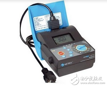
1. “Test line L†and “test line N†must not be connected incorrectly. The red test lead corresponds to L to 200V (fire line), the black test lead corresponds to N grounding pile, and sometimes the grounding pile is loose (poor grounding) will also cause the test to fail. Pay attention to distinguish!
2. When the “On/Off†button is turned on, if the indicator light is dark and the LCD screen is not displayed, it may be caused by insufficient battery. You can use the Phillips screwdriver to remove the battery back cover on the reverse side of the instrument and replace the battery of the same model ( 6v battery).
3, in the process of use, carrying, should be handled gently, not subject to strong bumps, vibration, crash, and should prevent the erosion of chemical reactants.
Dp Switcher,Hdmi Dp Switch,Dp Hdmi Switch,Switch Hdmi Dp
Dongguan Tuojun Electronic Technology Co., Ltd , https://www.fibercablessupplier.com