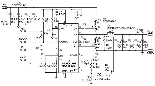
Key specificaTIons for the reference design are listed below, along with a detailed schemaTIc (Figure 1) and the bill of materials (Table 1) needed for this applicaTIon.
Specifications Input Voltage Range: 6.5V to 24V Output Voltage: 5V Output Current: 5A Output Voltage Ripple (pk-pk): 50mV Switching Frequency of Converter: 300kHz Overcurrent Protection Limit: 6A Efficiency:> 90% for Normal Operation

Figure 1. Schematic of the MAX15026 synchronous buck converter for a 300kHz switching frequency.
Table 1. Bill of Materials
| Designator | Value | Description | Part | Footprint | Manufacturer | Quantity |
| C1 | 220µF, 35V | Capacitor | EEVFK1V221P | 8mm x 10.2mm | Panasonic | 1 |
| C2, C3 | 4.7µF, 50V | Capacitor | GRM31CR71H475KA12L | 1206 | Murata | 2 |
| C4 | 0.1µF, 50V | Capacitor | GRM188R71H104KA93D | 0603 | Murata | 1 |
| C5 | 4.7µF, 6.3V | Capacitor | GRM188R60J475KE19D | 0603 | Murata | 1 |
| C6 | 2.2µF, 6.3V | Capacitor | GRM188R60J225KE19D | 0603 | Murata | 1 |
| C7 | 1µF, 50V | Capacitor | GRM21BR71H105KA12L | 0805 | Murata | 1 |
| C8 | 0.47µF, 16V | Capacitor | GRM188R71C474KA88D | 0603 | Murata | 1 |
| C9, C16 | 1200pF, 50V | Capacitor | GRM1885C1H122JA01D | 0603 | Murata | 2 |
| C10, C11 | 47µF, 10V | Capacitor | GRM32ER71A476KE15L | 1210 | Murata | 2 |
| C12, C13, C14 | 22µF, 10V | Capacitor | GRM31CR71A226KE15L | 1206 | Murata | 3 |
| C15 | 560pF, 50V | Capacitor | GRM1885C1H561JA01D | 0603 | Murata | 1 |
| C17 | 22pF, 50V | Capacitor | GRM1885C1H220JA01D | 0603 | Murata | 1 |
| R1 | 10Ω | Resistor | SMD 1% Resistor | 0603 | Vishay | 1 |
| R2 | 10kΩ | Resistor | SMD 1% Resistor | 0603 | Vishay | 1 |
| R3, R6 | 2.2Ω | Resistor | SMD 1% Resistor | 0603 | Vishay | 2 |
| R4 | 15kΩ | Resistor | SMD 1% Resistor | 0603 | Vishay | 1 |
| R5 | 56.2kΩ | Resistor | SMD 1% Resistor | 0603 | Vishay | 1 |
| R7 | 3.57Ω | Resistor | SMD 1% Resistor | 1206 | Vishay | 1 |
| R8 | 102kΩ | Resistor | SMD 1% Resistor | 0603 | Vishay | 1 |
| R9 | 13.7kΩ | Resistor | SMD 1% Resistor | 0603 | Vishay | 1 |
| R10 | 2.74kΩ | Resistor | SMD 1% Resistor | 0603 | Vishay | 1 |
| R11 | 47.5kΩ | Resistor | SMD 1% Resistor | 0603 | Vishay | 1 |
| L1 | 10µH ± 20%, 5.5A | Inductor | SLF12575T-100M5R4-PF | 12.5mm x 12.5mm x 7.5mm | TDK | 1 |
| N1 | 30V, 6.3A, 35.5mΩ-Q1; 30V, 8.6A, 16.5mΩ-Q2 | Dual MOSFET | FDS6982AS | 8-SO | Fairchild | 1 |
| U1 | PWM Controller | Low-Cost, DC-DC Synchronous Buck Controller with a 4.5V to 28V Operating Range | MAX15026BETD + | 14-TDFN-EP | Maxim | 1 |
Performance Data

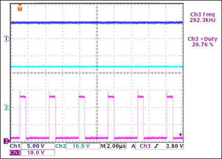
Figure 2. Steady-state output voltage, input voltage, and switching-node voltage at VIN = 24V, VOUT = 5V.
Ch1: VOUT; Ch2: VIN; Ch3: Lx Node Voltage

Figure 3. Enable, soft-start, soft-stop and PGOOD sequence waveforms.
Ch1: Enable; Ch2: VOUT; Ch3: PGOOD

Figure 4. Output and input ripples at VIN = 24V, VOUT = 5V and IOUT = 5A.
Ch1: Output Voltage Ripple; Ch2: Input Voltage Ripple

Figure 5. Converter load transient response with a 2A step change in load current.
Ch1: Output Voltage Dip; Ch2: Load-Step Change (1A / div)
Test ConditionsVIN = 12V, VOUT = 5V
Load Current Step Change: 1A to 3A
Load Current Slew Rate: 2A / µs

Figure 6. Hiccup-mode overcurrent protection with output shorted.
CH1: Output Voltage; CH2: Gate Pulses

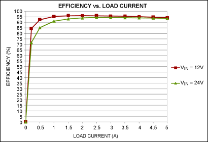
Figure 7. Efficiency vs. load current plots.
Fiber optic adapters are typically used to connect two fiber optic cables together. They come in versions to connect single fibers together (simplex), two fibers together (duplex), or sometimes four fibers together (quad). Adapters are designed for multimode or single-mode cables. The single-mode adapters provide more precise alignment of the tips of the connectors and can be used to connect multimode cables. The reverse is not suggested as this might cause misalignment of the small single-mode fibers and loss of signal strength (attenuation).
Optical attenuators are commonly used in fiber-optic communications, either to test power level margins by temporarily adding a calibrated amount of signal loss, or installed permanently to properly match transmitter and receiver levels. Sharp bends stress optic fibers and can cause losses. If a received signal is too strong a temporary fix is to wrap the cable around a pencil until the desired level of attenuation is achieved. However, such arrangements are unreliable, since the stressed fiber tends to break over time.
Types:
Optical attenuators can take a number of different forms and are typically classified as fixed or variable attenuators. What's more, they can be classified as LC, SC, ST, FC, MU, etc. according to the different types of connectors.
Sijee provides different types of Optical Fiber Attenuator, Fiber Optic Attenuator, Fiber Optic Fixed Attenuator, FC Fiber Attenuator.
Fiber Optic Attenuator
Optical Fiber Attenuator,Fiber Optic Attenuator,Fiber Optic Fixed Attenuator,FC Fiber Attenuator
Sijee Optical Communication Technology Co.,Ltd , https://www.sijee-optical.com