The "electronic swing" is simple to make, and it is equipped with toys such as white rabbits. Putting it in the proper position at home can add some fun to the living room. However, the author found that some "electronic swings" become unreliable after a long period of work, and some are repeatedly adjusted when they are used. After some trials, the author made this reliable and worry-free "electronic swing".
The "electronic swing" designed in this paper can automatically detect when the white rabbit is placed at the bottom, and quickly generate a magnetic field repulsive force, repudiating the white to avoid swinging high, and strong anti-interference ability.
First, the composition of the circuit
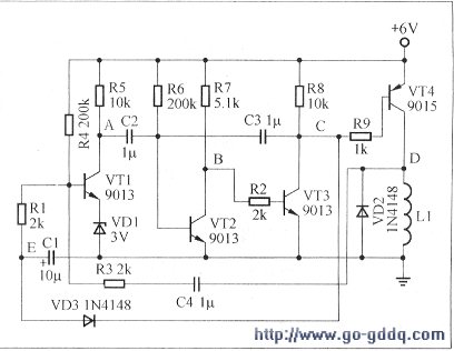
The circuit designed by the author is shown below.

The entire circuit consists of the following three parts:
1. Detection amplifier circuit: consists of L1, R3, C4, and a common emitter amplifier circuit composed of VT1, VD1, R4, R5, C2.
2. Monostable circuit: consists of VT2, VT3, and C3, R2, R6, R7, R8.
3. Drive circuit: mainly including R9, VT4, VD2, electromagnetic coil L1
Second, the working principle
The "Electronic Swing" uses the interaction between electrical energy, magnetic field energy and mechanical energy to drive the white to keep swinging.
The small magnet is placed at the bottom of the white rabbit. When the white rabbit is stationary, the vertical magnet of the small magnet is directly opposite the electromagnetic coil L1.
In the figure, four triodes are used, VT1 is in an amplified state, VT2 is in a saturated state, and VT3 and VT4 are in an off state most of the time.
Here, the electromagnetic coil L1 is skillfully utilized as both a driving device and a detecting element. In most cases, no current flows through L1. When the white rabbit passes over the electromagnetic coil L1, the electromagnetic coil L1 induces a voltage signal, which is transmitted from R3 and C4 to VT1, and is amplified by the VTI. When the polarity of both ends of the electromagnetic coil L1 is appropriately selected so that the white rabbit leaves from above the electromagnetic coil L1, the potential corresponding to the point A of the VT1 collector falls.
The drop of potential at point A, through the positive feedback of VT2 and VT3, makes VT2 cut off and VT3 saturated, and the monostable circuit composed of VT2 and VT3 enters the transient steady state. The transient steady-state time is determined by R6 and C3. According to the parameters in the figure, the transient steady-state time is about 0.5 second.
During the transient steady state, point C is low, so that the driving tube VT4 is saturated and turned on, and the driving electromagnetic coil L1 generates a magnetic field having the same polarity as that of the small white-free magnet, and the rabbit continues to oscillate under the action of the repulsive force of the magnetic field. .
During the transient state, the diode VD3 is turned on, and the capacitor C1 is rapidly discharged, so that the potential of the VTI base is reduced to less than 1V, and VT1 is turned off. This avoids interference from the electromagnetic coil L1, and the entire circuit does not form unnecessary oscillation.
After the transient steady state, the C point returns to a high potential, the drive tube VT4 is turned off, and the electromagnetic coil L1 has no current to pass, and no magnetic field is generated.
At this time, the diode VD3 is turned off, the capacitor C1 is charged, and the potential of the VT1 base is gradually increased. When it reaches 3.7V, the VT1 enters the amplification state again, preparing for the next work. Obviously, this delay time is determined by R4 and C1.
During the delay time, since the VTI is not turned on, no current is passed through the electromagnetic coil L1, and no magnetic field is generated.
Third, component selection
The parameters of the component are already marked in the figure. The resistors are all selected to be 0.25W.
The magnet mounted on the rabbit is a commercially available cylindrical NdFeB super magnet.
Electromagnetic coil L1 can purchase "electronic swing"
Dedicated coil. However, a good method is recommended here. You can use the coil of the 5V relay sold in the market to remove the core. Of course, it is necessary to ensure that the coil operating current is small, below 70 mA, and the generated magnetic field is strong enough.
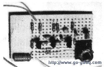
The actual board is shown on the right.

Fourth, the debugging method
The small magnet at the bottom of the small white is as close as possible to the electromagnetic coil L1 when it is at rest.
The debugging method is very simple. Turn on the power and push the white rabbit gently. The electronic swing starts to swing.
Silicon TVS / TSS:
Diode TVS (Transient Voltage Suppressor), also known as Transient suppression diodes, is widely used a new type of high efficient circuit protection device, it has a fast response time (the nanosecond) and high surge absorbing ability.When it ends of stand moments of high energy shock, TVS can bring the two ends at high rate from high impedance to a low impedance between impedance values, to absorb a large current moment, put it at both ends of the voltage restraint on a predetermined value, thus protecting the back of the circuit components are not affected by the impact of the transient high pressure spikes.
Silicon TVS Transient Voltage Suppresso,Silicon TSS Transient Voltage Suppresso
YANGZHOU POSITIONING TECH CO., LTD. , https://www.cndingweitech.com