Previously, we introduced the basics of decoupling and its importance in achieving the desired performance of integrated circuits (ICs). In this article, we will explore in detail the basic circuit components used for decoupling - capacitors.
 Actual capacitance and its parasitic effects
Figure 1 shows the model of the actual capacitance. The resistor RP represents the insulation resistance or leakage in parallel with the nominal capacitance (C). The second resistor, RS (equivalent series resistance or ESR), is placed in series with the capacitor and represents the resistance of the capacitor pin and capacitor plate.
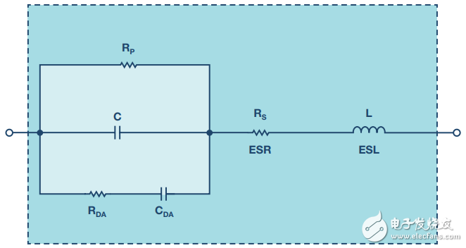
Figure 1. Actual capacitor equivalent circuit including parasitic components
Inductor L (equivalent series inductance or ESL) represents the inductance of the pin and capacitor plates. Finally, the resistor RDA and the capacitor CDA together form a simplified model called the dielectric absorption (DA) phenomenon. DA can cause errors when using capacitors in precision applications such as sample-and-hold amplifiers (SHAs). However, in decoupling applications, the DA of the capacitor is not important and is ignored.
Figure 2 shows the frequency response of different types of 100 μF capacitors. In theory, the impedance of an ideal capacitor monotonically decreases as the frequency increases. In practice, ESR flattens the impedance curve. As the frequency increases, the impedance begins to rise due to the ESL of the capacitor. The position and width of the "knee" will vary with capacitance, dielectric and capacitance values. Therefore, in decoupling applications, it is often seen that a larger value capacitor is connected in parallel with a smaller value capacitor. Smaller value capacitors typically have a lower ESL and still act like a capacitor at higher frequencies. The parallel combination of capacitors covers a wider frequency range than any of the capacitors in the combination.

Figure 2. Impedance of various 100μF capacitors
The self-resonant frequency of the capacitor is the frequency at which the capacitive reactance (1/ωC) is equal to the ESL reactance (ωESL). Solving this resonant frequency equation yields the following equation:

The impedance curves of all capacitors are similar to the general shape shown. Although the actual graph is different, the shape is roughly the same. The minimum impedance is determined by the ESR, and the high frequency region is determined by the ESL, which is largely affected by the package style.
 Decoupling capacitor type
With a wide range of values, high capacitance to volume ratio and wide operating voltage, the electrolytic capacitor series is an excellent cost-effective low-frequency filter component. The range includes universal aluminum electrolytic switch types that operate from less than 10 V up to approx. 500 V and range in size from 1 μF to thousands of μF (and a proportional form factor).
All electrolytic capacitors are polar and therefore cannot withstand reverse bias voltages above about 1 V without damage. Such components have relatively high leakage currents (possibly tens of μA), and the specific leakage current depends to a large extent on the particular series of designs, electrical dimensions, voltage ratings, and applied voltages. However, leakage current is unlikely to be a major factor in basic decoupling applications.
Universal aluminum electrolytic capacitors are not recommended for most decoupling applications. However, a subset of aluminum electrolytic capacitors are "switched" and are designed and specified to handle high pulse currents at frequencies up to hundreds of kHz with very low losses. These capacitors are directly comparable to solid tantalum capacitors in high frequency filtering applications and have a wider range of useful values.
Solid tantalum electrolytic capacitors are typically limited to 50 V or less and have a capacitance of 500 μF or less. At a given size, tantalum capacitors exhibit a higher capacitance to volume ratio than aluminum switch electrolytic capacitors, with a higher frequency range and lower ESR. Tantalum capacitors are also generally more expensive than aluminum electrolytic capacitors, and must be handled with care for surge and ripple currents. Recently, high performance aluminum electrolytic capacitors using organic or polymer electrolytes have also been introduced. These capacitor series have a slightly lower ESR and higher frequency range than other electrolytic types, and the low temperature ESR drop is also minimal. These components use labels such as aluminum polymers, specialty polymers, POSCAPTM and OS-CONTM.
Ceramic or multilayer ceramics (MLCC) are compact and low loss, and are typically the preferred capacitive material for several MHz. However, ceramic dielectric properties vary widely. For power decoupling applications, some types are better than others. Ceramic dielectric capacitors can be used up to a few μF with the X7R high-k dielectric formulation. The Z5U and Y5V models are rated for voltages up to 200 V. The X7R type has a smaller capacitance change under the DC bias voltage than the Z5U and Y5V types, so it is a better choice.
The NP0 (also known as COG) type uses a formulation with a lower dielectric constant with a nominal zero TC and a low voltage coefficient (unlike the less stable high K type). The usable value of the NP0 type is limited to 0.1 μF or lower, and 0.01 μF is a more practical upper limit value.
The extremely low inductance design of multilayer ceramic (MLCC) surface mount capacitors provides near-optimal RF bypass and is therefore increasingly used for bypassing and filtering at 10 MHz or higher. Smaller ceramic chip capacitors operate at frequencies up to 1 GHz. For these and other capacitors in high frequency applications, by choosing a capacitor with a self-resonant frequency above the highest target frequency, you can ensure that the useful values ​​meet your needs.
Thin film capacitors typically use windings that add inductance and are therefore not suitable for power supply decoupling applications. This type is more commonly used in audio applications where very low capacitance and voltage coefficients are required.
Finally, be sure to select a capacitor with a breakdown voltage of at least twice the supply voltage, otherwise an accident may occur when the circuit is powered up.
 Impact of poor decoupling technology on performance
Figure 3 shows the impulse response of the 1.58000 GHz high speed current feedback op amp AD8000. Both oscilloscope charts are obtained using an evaluation board. The left curve shows the correct decoupling response and the right curve shows the response after removing the decoupling capacitor on the same board. In both cases, the output load is 100 Ω.

Figure 3. Effect of decoupling on the performance of an AD8000 op amp
The oscilloscope diagram shows that the output exhibits poor ringing when there is no decoupling, mainly because the supply voltage is offset as the load current changes.
Now examine the impact of correct and incorrect decoupling on the AD9445, a 14-bit, 105 MSPS/125 MSPS high performance data converter ADC. Although converters usually do not have a PSRR specification, proper decoupling is still very important. Figure 4 shows the FFT output of the circuit being designed correctly. In this case, we use the evaluation board of the AD9445 - note that the spectrum is very clean.
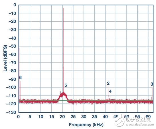
Figure 4. FFT plot of the AD9445 evaluation board with proper decoupling
The pinout of the AD9445 is shown in Figure 5. Note that there are multiple power and ground pins. This is to reduce the power supply impedance (parallel pins).
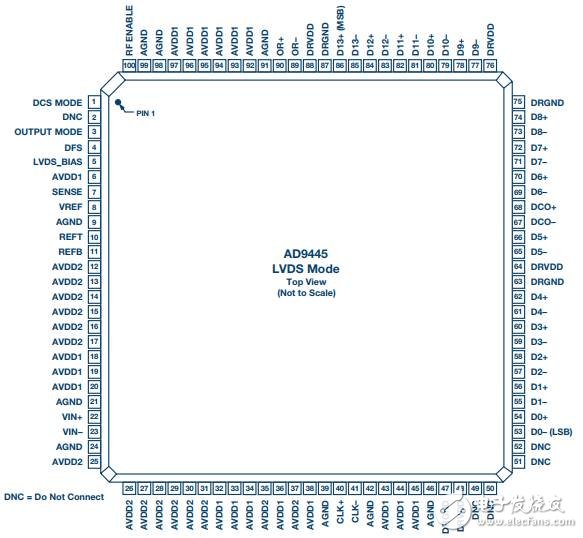
Figure 5. Pinout of the AD9445 from the AD9445 data sheet
There are 33 analog power pins. The 18 pins are connected to AVDD1 (3.3 V ±5%) and the 15 pins are connected to AVDD2 (5 V ± 5%). There are 4 DVDD (5 V ± 5% voltage) pins. In the evaluation board used in this experiment, each pin has a 0.1μF ceramic decoupling capacitor. In addition, there are several 10 μF electrolytic capacitors along the power trace.
Figure 6 shows the spectrum after removing the decoupling capacitor from the analog supply. Note that the high frequency spurious signal is increased and some intermodulation products (low frequency components) appear. The signal SNR has been significantly reduced. The only difference between this figure and the above figure is the removal of the decoupling capacitor.
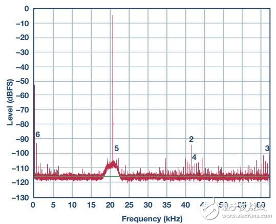
Figure 6. FFT plot of the AD9445 evaluation board after removing the decoupling capacitor from the analog supply
Figure 7 shows the result of removing the decoupling capacitor from the digital power supply. Note that the spurs also increase. Also pay attention to the frequency distribution of the spurs. These spurs not only appear at high frequencies, but also span the entire spectrum. This experiment was performed using the LVDS version of the converter. As you can imagine, the CMOS version will be even worse because the noise of LVDS is lower than that of saturated CMOS logic.
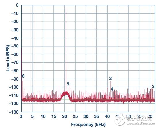
Figure 7. SNR plot of the AD9445 evaluation board after removing the decoupling capacitor from the digital supply
These experiments show that removing most or all of the decoupling capacitors can cause performance degradation, but it is difficult to analyze or predict the effects of removing one or two decoupling capacitors. When you can't decide, the best strategy is to put a capacitor. Although the cost is slightly increased, the risk of performance degradation is eliminated, which is usually worthwhile.
 Decoupling summary
There is still a lot of content about decoupling, but we hope that everyone has a general understanding of its role in achieving system expectations.
Another valuable resource for guidance is the manufacturer's evaluation board, and most IC products have corresponding evaluation boards. In many cases, you only need to download the schematic, layout, and component lists, and then learn what to do with decoupling without having to actually purchase the evaluation board. You can be confident that these evaluation boards are designed with great care in mind to achieve the best performance of the IC to be evaluated.
HQD Disposable Vape, HQD Disposable E-Cigarette, HQD Disposable Vape Supplier
Shenzhen Uscool Technology Co., Ltd , https://www.uscoolvape.com