With the development of society, China's population is becoming more and more aging, and the supervision of the elderly has become a social problem. According to the characteristics of the elderly guardianship, this paper uses the Beidou satellite positioning system independently developed by China, and combines the Beidou positioning module BDM100 to design two family monitoring terminal solutions for different needs, which are used for real-time positioning of the elderly and transmit real-time location information. In the hands of the supervisor. The first scheme adopts the EVDO module MC8630 supporting 3G network, and combines the AT91SAM9260 chip with ARM9 as the core to carry out position information backhaul. This scheme has the characteristics of rapid transmission and strong scalability, which can provide physical information and environmental information for later transmission. Expand the space. The second scheme adopts the GSM module GTM900 supporting 2G network, and combines the LPC1766 chip with Cortex-M3 as the core for positioning information transmission. This scheme combines good software design with low cost and stable performance. After experimental testing, these two solutions can solve the real-time positioning problem of the elderly in the family monitoring.
1 BDM100 module designThe BDM100 module is a dual-system high-performance GNSS module that can support both BD2 B1 and GPS L1 frequencies. It is well suited for low-cost, low-power applications and can be used for large-scale Beidou system integration applications. The block diagram of the module is shown below:
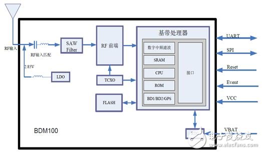
Figure 1 BDM100 module structure block diagram
As can be seen from the block diagram of the chip structure, the BDM100 supports various interfaces such as UART, SPI, 1PPS, and I2C. It can be matched by correlator, FFT and matched filter and algorithm optimization to maintain excellent capture tracking and fast TTFF in a variety of complex environments. The use of multi-path suppression technology and high-quality raw observation data can ensure good timing and navigation accuracy. The BDM100 chip can adopt multi-system hybrid positioning method, which can improve the positioning accuracy. Because the Beidou positioning system is adopted in this paper, only the Beidou positioning function is selected. In addition, the BDM100 chip has three serial ports, users can set their own baud rate, the default baud rate is 9600, and firmware upgrade through serial port 3. The module's positioning accuracy can reach 3 meters, and the speed measurement accuracy can reach 0.1 m / sec. The peripheral application circuit diagram adopted by this system is as follows:
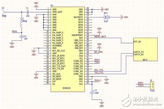
Figure 2 BDM100 module peripheral circuit diagram
Both solutions of the system use serial port 1 to communicate with the MCU, and the serial port 3 reserves an interface for later upgrade. Special Note: When the module starts normally, keep the serial port 3 input pin level high during the reset signal valid period, otherwise the module will enter the upgrade firmware mode and cannot start normally. The module reset signal is active low and must be no longer than 2 milliseconds; the module must be equipped with an antenna of +2.85V active antenna, the antenna is connected to the GNSS_ANT pin of the module, and the active antenna is internally integrated with LNA (Low Noise Amplifier) It can be directly connected to the GNSS_ANT pin of the module. If an active antenna other than +2.85V is used, the antenna needs to be powered.
In the software interface protocol adopted by the BDM100 module used herein, the information is mainly transmitted through the delivery of a message, wherein the "message" is a string composed of a full ASCLL code. The basic format of the message is:

Table 1 BDM100 module message format
All of the messages start with $(0x24) followed by the message name followed by an indefinite number of parameters or data. Message names and data are separated by a comma (0x2C). The message indicating the input can end with ''(0x0D) or ''(0x0A) or any combination of the two, and the message indicating the output ends with the combination of ''. The letters in the message name and parameters are not case sensitive.
The BDM100 module needs to be initialized before use. The initialization process is the process of message interaction between the module and the master chip. The BDM100 module has timing and positioning functions. The system only uses its positioning function, so the initialization of the timing function is not described.
The initialization instructions required for this system are shown in the following table:

Table 2 BDM100 module initialization instructions
In the 3G solution, because the USB interface is used for communication, the baud rate needs to be set to 115200 (the default baud rate is 9600). The specific commands are: $CFGPRT, 3, h0, 115200, 3, 3. Because the system uses the Beidou positioning system, and the BDM100 module can support the GPS and Beidou hybrid positioning, the module needs to be set to the Beidou positioning mode during initialization. It can be implemented by two commands—CFGSYS/CFGNAV. The specific commands are: $CFGSYS, h10 or $CFGNAV, 1000, 1000, 3, 2. There are many kinds of messages for output. The specific codes are as follows:

Table 3 BDM100 module message type list
The output used in the system needs geographic location information and corresponding time information. It can be seen from the above message type that the GLL message or the RMC message can satisfy the requirement, because the GLL message is shorter than the RMC message, and the information efficiency is relatively high, so The system uses GLL messages for transmission in the design. Due to the limitation of the processing capability of the control chip connected in the scheme, the GLL message needs to set its output frequency to 1 time/second, and its corresponding category and ID number are 0 and 1, respectively, and the highest GLL message is obtained by searching the corresponding chip software manual. The output frequency is 1 Hz, so the specific command to set its frequency using CFGMSG is: $CFGMSG, 0, 0, 1.
When the above content is processed, you need to save the settings. The command used is: $CFGSAVE.
After the initialization is completed, the BDM100 chip will output data through the interface at a rate of 1 time/second. The specific receiving and processing process is processed by the master chip linked with it.
2.3G scheme design and implementationThe monitoring terminal designed with 3G scheme adopts ARM926EJ-S as the core of AT91SAM9260 chip as the main control chip. The chip has stable performance, rich peripheral interfaces, embedded Ethernet, fast RAM and ROM, and supports the characteristics of LINUX operating system. The 3G chip returned by the message adopts the EVDO module MC8630. The 3G service requires the network to have high data throughput. The EVDO module supports the data packet service provided by China Telecom CDMA2000. For the wireless data access service, the access speed of the EVDO is close. The level of limited ADSL Internet access, and in this way, the data transmission is stable, leaving room for future performance expansion, meeting the design requirements of the program.
2.1 hardware design
The BDM100 module and the main control chip AT91SAM9260 are connected through the UART interface, and the 3G chip MC8630 is connected to the main control chip through the USB port, so that while ensuring the stability of reception and transmission, it can also provide space for future performance expansion. The specific circuit for connecting the BDM100 module and the main control chip is shown in Figure 2. The connection between the 3G module and the main control chip is shown in the following figure:
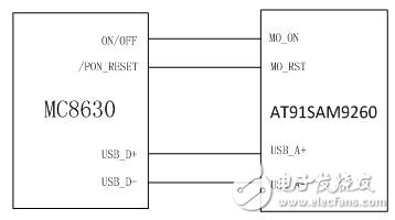
Figure 4 3G module and main control chip connection diagram
2.2 Software Design
Linux is used as the operating system on the main control chip AT91SAM9260. The operating system has been used on many embedded devices, and its stability has been verified.
2.2.1 Connection of BDM100 module
The BDM100 module uses the UART serial port to communicate with the main control chip. After the kernel is configured in linux, the serial communication interface is used for initialization and positioning information transmission. In this solution, the specific serial communication function is as follows:
When serial communication is performed, the serial port must be initialized first, and the Serial_init function is executed correspondingly.
Specific format:
Int serial_init(char *dev, int speed, int is_block)
Where dev is the device file address, speed is the serial port baud rate, and is_block is set to prevent blocking when the initialization is unsuccessful until the initialization is successful.
The initialization function opens the device file by calling the staTIc int open_dev(char *dev, int is_block) function, where the dev and is_block parameters have the same meaning as the initialization function. Open successfully, return device file descriptor, otherwise return -1. The baud rate is set by calling staTIc void set_speed(int fd, int speed), where fd is the device descriptor and speed is the rate. When this function is called, the serial port is stopped.
After the initialization is completed, the data can be read and written. The read function is:
Int serial_read_TImeout(int fd, char *str, unsigned int len, unsigned int TImeout/*ms*/)
This read function is a serial port read with a timeout mechanism. The received data is placed in the string of str, fd is the device file address, len is the length of the read, timeout is the timeout, the ms level, and the function returns the length of the read. .
The so-called timeout mechanism means that when the program uses this function to read data, it will start a thread, run when there is data, block when there is no data, when the thread has data, read the data, the program continues, if the timeout has not been read Finish, then give up reading, the program continues, generally within the set time, the program can read the data, this is to prevent the thread from deadlock, unable to end the thread.
The specific format of the serial port send function is:
Int serial_send(int fd,char *str,unsigned int len)
Where fd represents the device file address, and the send data is placed in str with a length of len. The transmission returns the transmission length successfully, otherwise it returns a value less than 0.
Through such three functions, the communication between the BDM100 module and the main control chip AT91SAM9260 can be realized, and the related module initialization operation and information transmission can be completed.
2.2.2 Connection of MC8630 Module
The EVDO RF module used in this solution cannot be identified at first, because this option is not turned on in the default configuration of Linux. It is a custom circuit, so it needs to be manually configured. According to the circuit diagram of the MC8630 module, the CPU communicates with the MC8630 through the USB port. Therefore, the USB port of the processor needs to be configured as a 3G function. Linux driver support for 3G modules is mainly to convert USB to serial port, and the application can operate USB like the serial port.
Therefore, in addition to the "USB driver for GSM and CDMA modems" kernel option, you need to open the USB function and USB to serial port conversion support in the kernel option. The 3G module also uses third-party dial-up software, so you need to open PPP dial-up. Function, after configuration, compile the kernel. After burning the system, reboot into the /dev directory. If the four device files USBtty0~USBtty3 appear, it indicates that the driver of the 3G module has been loaded correctly. details as follows:
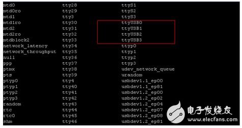
Figure 5 3G module driver loading
When the program is initialized, the PPP0 network card is bound by the prepared dialing script, so that the program can operate the 3G module like the local network card, and use the socket mechanism to transmit the message. The specific dialing script is as follows:
If ['ifconfig|grep ppp0|awk '(print($1))'']
Then
Echo "the ppp0 has existed!"
Else
Pppd call evdo &
Until['ifconfig|grep ppp0|awk '(print($1))'']
Do
Sleep 1
Done
Route del default
Route add default dev ppp0
Fi
After executing the ifconfig command, the system will list all the network cards. In general, there are only two NICs, eth0 and lo: eth0 is the network port of the commonly used RJ45 interface. Plug in the ordinary network cable to access the Internet; lo is the local network card; After using pppd to dial up successfully, the ppp0 wireless network card will appear, and the 3G module is connected to the Internet. However, when the operating system starts, the default default network card is eth0. Therefore, after the dialing is successful, the default routing path must be modified. If the specified network card is not bound when the application uses socket programming, all network data will be from the ppp0 network card. transmission. After binding the ppp0 network card, you can use the linux socket mechanism to communicate with the background server. The UDP method used in this solution communicates with the background server. The communication of the UDP protocol does not need to establish a link in advance like TCP, only the ip address needs to be bound. And the port number can be, but in this scheme, for the future scalability, the socket_connect and socket_send functions are designed. Whether it is TCP or UDP, just call these two functions, use the same interface, so that it is easy to use and extend the function. . details as follows:
Int socket_connect(const int sock_fd, const char *ip_str, const unsigned int port_ui)
Where sock_fd is a socket, which is created by the function int socket_create(const int af, const int type, const int protocol, const int stime, const int rtime, const char *ifname). Ip_str is the ip address and port_ui is the port number.
Int socket_send(const int sock_fd, const char * data, const int len, const int flags)
Where data is the data to be sent, len is the length, and flags are generally taken as 0.
Receive function:
Int socket_recv_timeout(int sock_fd, char *buff, unsigned int len, unsigned int timeout/*ms*/)
The specific function is used to receive network data until the length is equal to len, or return after timeout.
2.2.3 Server and 3G Module Communication Protocol
After receiving the message sent by the BDM100 module, the main control chip AT91SAM9260 will reassemble the message and send it to the background for resolution through the 3G module. Because the positioning terminal of the system has real-time performance, the demand for the year, month and day information is not very emphasized. Therefore, when the Beidou is initialized, it receives the GLL information, which only contains information of time, minute and second. The message communication protocol adopted in this scheme is as follows:

Table 4 Custom Communication Protocol
The start bit and the check bit are both represented by unsigned short, and the check uses an exclusive OR operation of every two bytes. At compile time, two bytes are aligned and compiled.
The 3G module uses this format to transmit messages to the backend server for processing, which is beneficial to keep the information stable and concise.
3. 2G solution design and implementationThe monitoring terminal designed by 2G scheme adopts LPC1766 based on cortex-M3 as the main control chip, and the 2G module adopts GTM900 chip supporting GSM network [4]. The 2G network technology adopted by the solution is mature and stable, and the speed can also meet the information transmission requirements. With the robust software design, it achieves good results in specific applications.
3.1 Hardware Design
The specific hardware connections of the program are as follows:

Figure 6 2G scheme block diagram
It can be seen from the figure that the BDM100 chip and the GTM900 chip are connected to the main control chip LPC1766 through the serial port 1 and the serial port 0 respectively. The connection between the GTM900 and the LPC1766 only needs to connect the TXD pin to the RXD0, the RXD to the TXD0, and then the two. The GNDs of the chips can be grounded. The connection corresponding to BDM100 and LPC1766 can be directly shown in Figure 2.
3.2 Software Design
In the software design of the 2G solution, since the operating system is not used, the bare program is designed directly according to the instruction manual of the LPC1766 and the other two chips. The first is to initialize the BDM100 chip and the GTM900 chip. Here, the initialization operation of the GTM900 chip is before the BDM100 chip. Because the BDM100 directly outputs the position information GLL after initialization, in the program design of this solution, only one is set. Receive the global array variable RecUartBuf[100] of the serial port data. If the BDM100 chip is initialized first, the GLL information will conflict with the GTM900 initialization information. In addition, in the UART receiving program, since the data length received each time is not fixed, it cannot be set to a multi-byte interrupt. In this scheme, the program is set to a one-byte interrupt, and a timer interrupt is set to determine the data. Whether the transmission is completed or not. In the previous BDM100 chip introduction, set the frequency of the location information GLL to 1 time/second, then set the timer interrupt to 0.5s in this scheme, so that there is enough time to receive and transmit information. In the timer interrupt function, the information flag variable RecUartFlag is set to 1, indicating that data is entered. At this time, the GLL information transmitted by the Uart0Sent function is sent to the background server through the 2G module.
In this solution, because the program robustness is required, the format of the GLL location location message transmitted to the background server is the original information that is not reorganized, and the information reorganization and parsing tasks are handed over to the background server program for processing.
4. System testingAfter the data of the monitoring terminal is transmitted to the server through the 3G or 2G network, the server parses it according to the communication protocol. After getting the data, the server does the following:
1) Check whether the data is wrong, discard it if there is an error, and ask the terminal to reacquire the information and transmit it immediately.
2) Reorganize and restore according to the values ​​in the data to get the latitude and longitude and the current time (in the format: XX XX minutes XX seconds).
3) According to the latitude and longitude information, call the map service to get the specific location.
4.1 3G solution test
The Beidou positioning information obtained through the serial port software is as follows:
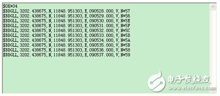
Figure 7 Beidou information serial port software display
It shows that the north latitude is 32 degrees 0,243,875 points, the east longitude is 118 degrees, 48,951,303 minutes, and the latter 090528 points indicate the UTC time. In order to unify the format, the MM degree XX division format is converted into MM.NN points (1 degree is equal to 60 points), so 118 degrees 48951303 points is equivalent to 118.81585505 degrees, and 32 degrees 02438575 points is equivalent to 32.04064458 degrees. The UTC time is equivalent to the time in the 0 time zone, corresponding to the time of the Beijing time as the East 8th district, so it is the standard Beijing time to add 8 hours. The UTC time format of the GLL message displayed by the BDM100 software interface protocol is XX. The time is XX minutes and XX seconds, for example, 090528, the corresponding UTC time is 9:5:28, and the corresponding Beijing time is 17:5:28. The background server program displays the message:
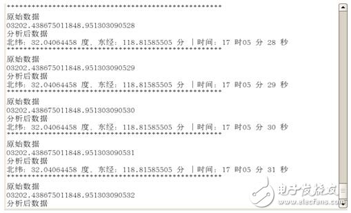
Figure 8 Beidou information 3G server side display
It can be seen from the figure that it is consistent with the serial communication software display message, which verifies the availability and stability of the system.
4.2 2G solution test
Also use the serial communication software to get the GLL message again:
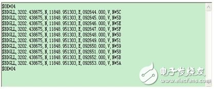
Figure 9 Beidou information serial port software display
The background server program displays the message:
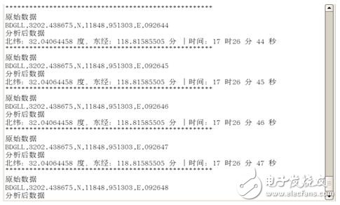
Figure 10 Beidou information 2G server display
It can be seen from the figure that the message is consistent with the serial communication software, which verifies the feasibility of the 2G solution.
In order to verify the accuracy of the positioning, open the Earth Online (http://), enter the current latitude and longitude information, and check the positioning.
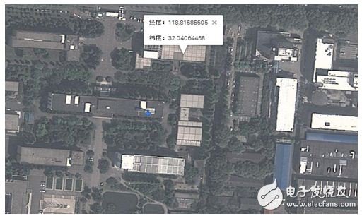
Figure 11 Beidou information positioning test
As shown in the figure, the position of the Beidou is A12, and the location of the author is the A10 building with the blue mark in the picture. The error is about 30 meters. Due to the free version of the goole map, the official declaration is 50 meters. Within, so the error of this test is within a reasonable range, indicating that the positioning terminal based on the Beidou BDM100 module is running successfully.
ConclusionAs a global satellite positioning system independently developed by China, the Beidou satellite positioning system is also constantly improving the civilization process. This paper designs two solutions to solve the problem of location location in home monitoring. The 3G solution can not only transmit Location information also provides an interface and expandable space for future transmission of various body information. The advantage of the 2G solution is that its performance is stable and the cost is low, which is a good choice for users with a single requirement. These two schemes are reasonable in design and stable in performance, and have certain reference value for other engineering designs.
Insulated Copper Tube Terminals
Insulated Copper Tube Terminals,High quality insulated terminal,copper tube terminal
Taixing Longyi Terminals Co.,Ltd. , https://www.longyicopperterminals.com