Generally, both the DSP and the MCU provide a corresponding serial port to communicate with other processors, which makes communication between multiple processors possible. In addition, in many field test situations, engineers need to obtain a hard copy of some form of measurement results, so that they can be used as reference materials in the future, or when the device reports an error action, it is necessary to view the previous data. In many cases, we need to pass the signals from the test instrument to the PC. In other cases, we may want to use a PC to control the test instrument, both of which require communication capabilities. In other words, we must have communication hardware and its supporting software when designing the instrument. We call this communication software and hardware an "interface."
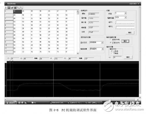
The first function of the P0.0 and P0.1 ports of the ARM single-chip LPC2138 used in the system designed by this subject is the ARM serial communication interface. Using the serial communication interface of ARM, the serial port to USB interface switching module has been designed, through the PC. The machine's USB interface is implemented. The purpose of adding the auxiliary debugging function of the host computer in the design of the system is as follows:
Before the installation, the main functions of the power analyzer channel quality, FPGA control, ARM main algorithm and other systems are debugged. In the case of not being connected to an external input device such as a liquid crystal display or a keyboard, the designer can still visually observe the system measurement results, facilitating targeted debugging.
Updates to system parameters such as calibration tables. Due to the large amount of data in the calibration table, it is very time consuming to input the keyboard one by one according to the external command input characteristics of the instrument. The upper layer software provides a data input form, and the calibration value is directly attached to the table, and the calibration table can be written into the FLASH of the ARM at one time, and when the calibration table needs to be changed when the device is used, only the connection line is used to access the computer. , you can update the calibration table.

As shown in Figure 4-6 above, the host computer auxiliary debugging software design all functions of the power analyzer, and utilizes the features of high-level software programming freedom and convenient operation and control of the upper computer, which can well meet the system debugging and batch writing of the calibration table. And the main functions of human-computer interaction.
LCD controlWith the rise of the communications, IT and multimedia markets, low power consumption, low radiation, and easy-to-carry liquid crystal display (LCD) have become the first choice for handheld instruments. Compared with CRT, liquid crystal has the following advantages:
â—† Low power consumption. Very low operating voltage, only 3 ~ 5V, working current is several UA / (cm) * 2. Therefore, the liquid crystal display can be directly matched with large-scale integrated circuits, making portable electronic computers and electronic instruments possible.
â—† Flat structure. The basic structure of the liquid crystal display is a sandwich case composed of two sheets of glass. The advantage of this structure is that it is most convenient to use, and it is practical for large, small and miniature.
â—† Passive display type. The liquid crystal display itself does not emit light but is modulated by modulating external light.
â—† Display information is large. Compared to the CRT display, the liquid crystal display has no shadow mask limitation, and the pixels can be made small, which is for the future high definition television. It is an ideal choice.
â—† Easy to colorize. Liquid crystal colorization is very easy, and there are many methods. What is more valuable is that the color of the liquid crystal can be reproduced very accurately on the chromatogram, and therefore, color distortion is not generated.
â—† When the LCD display is working, there is no electromagnetic radiation.
â—† Long life. The device itself has almost no degradation problems. Therefore, the life is extremely long.
This project selects the black and white display of TRULY model MSP-G320240DBCW. It is a 320&TImes; 240 dot matrix LCD. The LCD display integrates the SED1335 liquid crystal display controller, which greatly facilitates the display control of the liquid crystal display.
BLPS laser safety protective device is designed for personal safety used on hydraulic bender.
The dynamic test technology it used has passed the Type 4 functional safety assessment by TUV, and get the national invention patent. The product reaches the advanced technological level of similar products.
BLPS laser safety device provides protection zone near the die tip of the bender to protect fingers and arms of the operator in close to the upper mold die tip. It is the most effective solution so far to preserves the safety and productivity of the bender.
Press Brake Protection,Laser Guarding Device,Press Brake Guarding Systems,Press Brake Guarding
Jining KeLi Photoelectronic Industrial Co.,Ltd , https://www.sdkelien.com