Designers with deep digital electronics knowledge sometimes need to review the RF basics. Among them, the RF filter is used in electronic equipment for high-frequency operation, and is used for a large attenuation of high-frequency interference signals generated by high-frequency electronic equipment. Therefore, the choice of RF filter is of great significance to electronic equipment. This article can help engineers correctly find the filter that meets the specific application by quickly revisiting some important foundations of the filter performance parameters.
1. Understand the basic response curveThe basic response curves of the filter include: bandpass, lowpass, highpass, bandstop, duplexer, as shown in Figures 1A-1F. Each specific shape determines which frequencies pass and which cannot.
Undoubtedly, the most common of these groups is the bandpass filter. All engineers know that a bandpass filter allows signals between two specific frequencies to pass, suppressing signals at other frequencies. For example, surface acoustic wave filters (SAW), crystal filters, ceramics and cavity filters. For reference, the cavity bandpass filter manufactured by Anatech Electronics has a frequency range of 15 MHz to 20 GHz and a bandwidth in the range of 1% to 100%. The table below gives all the technical parameters of the lumped component bandpass filter from Anatech Electronics. All manufacturers have adopted a method of defining the passband with 0.5 dB, 1 dB or 3 dB attenuation points on either side of the filter center frequency.
2, including all necessary technical parametersThis often happens, and engineers give a short request for a "100 MHz bandpass filter," which is clearly too small. It is difficult for filter suppliers to sign orders based on such information.
Give all the necessary information starting with giving all the frequency parameters in detail, such as:
Center Frequency (Fo): The midpoint between two 3 dB points, usually defined as a bandpass filter (or bandstop filter), typically expressed as the arithmetic mean of two 3 dB points.
Cutoff Frequency (Fc): The transition point from the passband to the stopband of the lowpass filter or highpass filter, which is typically 3 dB points.
Suppression frequency: A particular frequency or group of frequencies at which a signal attenuates certain specific values ​​or sets of values. Sometimes the frequency region outside the ideal passband is defined as the suppression frequency or frequency group, and the attenuation passed is called suppression.
The filter type determines the specific frequency. For bandpass and bandstop filters, the specific frequency is the center frequency. For low pass and high pass filters, the specific frequency is the cutoff frequency.
For the sake of completeness, engineers should also define the following features, such as:
Stopband: The frequency band between specific frequency values ​​that the filter does not transmit.
Isolation: In the duplexer, the ability to suppress the transmission (Tx) frequency when considering the reception (Rx) channel, and the ability to suppress the reception (Rx) frequency when considering the transmission (Tx) frequency, is called Rx/Tx isolation. The higher the isolation, the stronger the filter's ability to isolate the Rx signal from the Tx signal, and vice versa. The result is a smoother transmission and reception signal.
Insertion Loss (IL): A value indicating the power loss in the device, IL = 10Log(Pl/Pin), independent of frequency, where Pl is the load power and Pin is the power input from the generator.
Return Loss (RL): A measure of filter performance that indicates how close the filter input and output impedance are to the ideal impedance value. The return loss is defined as: RL = 10Log(Pr/Pin), independent of frequency, where Pr is the power reflected back to the generator.
Group Delay (GD): The group delay represents the magnitude of the phase linearity of the device. Since the phase delay appears at the output of the filter, it is important to know if this phase shift is linear with changes in frequency. If the phase shift varies nonlinearly with frequency, the output waveform will be distorted. Group delay is defined as the derivative of the phase shift as a function of frequency. Since the derivative of the linear function is constant, the group delay caused by the linear phase shift is constant.
Shape Factor (SF): The shape factor of a filter is typically the ratio of the stopband bandwidth (BW) to the 3 dB bandwidth. It is a measure of the steepness of the edge of the filter. For example, if the 40 dB bandwidth is 40 MHz and the 3 dB bandwidth is 10 MHz, the form factor is 40/10=4.
Impedance: Filter source impedance (input) and termination impedance (output) in ohms. In general, the input impedance and output impedance are the same.
Relative attenuation: The difference between the measured attenuation at the minimum attenuation point and the attenuation of the ideal suppression point. Typically, relative attenuation is expressed in dBc.
Ripple (Ar): Indicates the flatness of the filter passband, usually expressed in decibels. The size of the filter ripple affects the return loss. The larger the ripple, the more severe the return loss and vice versa.
Suppression: Ibid.
Operating temperature: The operating temperature range of the filter design.
3. Don't pursue unrealistic filter characteristicsEngineers sometimes ask for the following: "I need a passband of 1,490 to 1,510 MHz, and a suppression of 70 dB at 1,511 MHz." This requirement cannot be achieved. In fact, the suppression is gradual, not a sharp drop of 90°, and the more practical parameter is about 10% off center frequency.
Another situation is that the filter is required to, for example, "suppress all components above the frequency of 1,960 MHz." At this point, the engineer must be aware that it is not possible to attenuate the rejection frequency until all frequencies between infinitely high frequencies. Some boundaries must be set. A more realistic approach might be to attenuate the specific rejection frequency near the passband by two to three times.
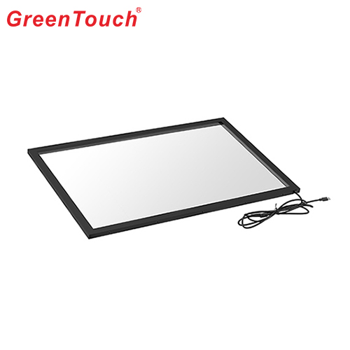
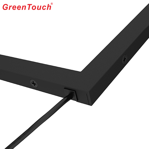
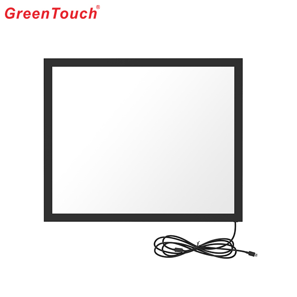
GreenTouch infrared touch screen uses the high quality of transparent glass so it has excellent clarity, resolution, light transmittance and reliability. Even though there are some scratches on the surface of glass,it can still work normally. The surface of the screen has no surface coating on the plastic film or moving parts, so there is no parts will wear consumption during the usage.infrared touchscreen ensures stable performance without any ghost spots or drift.The operation is sensitive, through finger, glove, passive stylus and other opaque objects can perform accurate touch input. a high-precision IR Touch Screen.
Pictures show:


Multi Point Infrared Touch Screen,Smart ​Infrared Touch Screen,Infrared Touch Frame Technology,Touch Screen Frame For Tv,Infrared Touch Screen Panel,IR Touch Screen
ShenZhen GreenTouch Technology Co.,Ltd , https://www.bbstouch.com