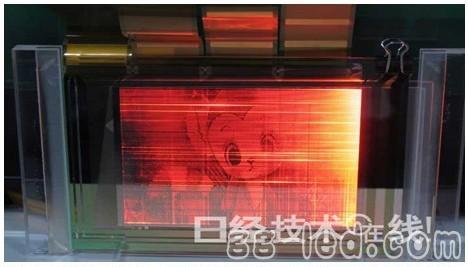
From the published content, if the previous prototype is exposed to the air, as the cathode is continuously oxidized, the light-emitting area will be reduced to 1/2 after 100 days, and the components of this time are hardly deteriorated. In this case, the cost of the sealing material used outside the component may be lowered.
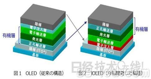
The OLED elements developed by NHK and Japan Catalyst adopt an "inversed OLED" (iOLED) structure, which is opposite to the inter-electrode element structure of the bottom-emitting type element. Specifically, an electron injecting layer, an electron transporting layer, a light emitting layer, a hole transporting layer, and an anode (titanium, gold, or the like) are sequentially formed on a transparent substrate/transparent cathode (ITO). In general, a bottom-emitting OLED device is formed by forming a hole transport layer (PEDOT: PSS, etc.), a light-emitting layer, an electron transport layer, and an electron injection layer on a transparent substrate such as glass/transparent anode (ITO or the like). A cathode (aluminum or the like) is formed.

To this end, NHK and Nippon Shoku decided to use other materials in the electron injection layer. However, most other materials are "sputtered" using a high-energy manufacturing process, which destroys the already formed electron transport layer and luminescent layer. Therefore, the two companies chose an iOLED structure that can form an electron injection layer before forming an electron transport layer.

However, for the electron injecting layer material that replaces LiF, NHK only discloses "materials that are not easily oxidized and have high integration with ITO in terms of work function". Prior to this, OLED development rarely used iOLED construction, precisely because of the poor integration of the two, "it is difficult to use ITO as a cathode."
In terms of durability comparison, the two sides conducted experiments in which the following three components were placed in a normal temperature air environment for comparison. The three components are: (1) a light-emitting side using a glass substrate, a back surface sealed with a common resin-based material, and a component having a normal bottom-emitting structure; (2) the same sealing method, using an iOLED structure, an electron injecting layer material A (3) The same sealing method, using the iOLED structure, the component of the electron injection layer material B.
As a result, it was revealed that (1) a non-luminous dark spot representing deterioration was apparently started after 20 days, and after 100 days, 1/2 of the light-emitting portion had deteriorated. (2) Deterioration began to become apparent after 40 days. And (3) no deterioration was found after more than 100 days.
According to the above results, the use of the iOLED structure like the element (2) does not sufficiently improve the durability, and in addition to the iOLED structure, the selection of the material of the electron injection layer is also an important condition for improving the durability.

Aerial Insulated Cables Within Rated Voltage Up To Including 0.6/1KV
1. Product standard
The product is manufactured according to the standards of GB12527-90 [Aerial insulated cables of rated voltages up to and including 1KV" and IEC60502 [Extruded solid dielectric power cables for rated voltage from 1KV to 30KV" .
2. Operating characteristics
a. Rated voltage U0/U: 0.6/1kV
b. Max.permissible continuous temperature:
PVC.PE insulated aerial cables:70℃
XLPE insulated aerial cables:90℃
c. Max. short-circuit temperature of the conductor shall not exceed:
PVC insulated aerial cables:160℃;
PE insulated aerial cables:130℃;
XLPE insulated aerial cables:250℃.
d. The installation ambient temperature should not below -20℃.
The bending radiuses of cables are recommended as follows:
When the diameter of cables less than 25mm: not less than 4 times the diameter of cables;
When the diameter of cables not less than 25mm: not less than 6 times the diameter of cables.
e. When the cables use in alternating current system, rated voltage of cables should be at least equal the rated voltage of the system; When the cables use in direct current system, rated voltage should be not greater than 1.5 times of the rated voltage of the cables.
3. Type of cables and main usage
Type of cable:
JKV: Copper conductor PVC insulated aerial cables
JKLV: Aluminum conductor PVC insulated aerial cables
JKY: Copper conductor PE insulated aerial cables
JKLY: Aluminum conductor PE insulated aerial cables
JKYJ: Copper conductor XLPE insulated aerial cables
JKLGV: ACSR conductor PVC insulated aerial cables
JKLGY: ACSR conductor PE insulated aerial cables
JKLGYJ: ACSR conductor XLPE insulated aerial cables
Main usage:
The cables fit for overhead fixed-installation, service line and so on.
4. Construction of cable
1) Conductor
2) Steel core
3) Insulation
4) Conducor screen
Steel ACSR Power Cable,Hot Dip Galvanized Power Cable,Conductor Power Cable,Overhead Power Cable
Huayuan Gaoke Cable Co.,Ltd. , https://www.bjhygkcable.com