How does the radar detect echoes from multiple different targets simultaneously and then classify them according to the Doppler frequency? In principle, it is very simple, that is, the echo signal received by the radar is realized by a set of digital filters called Doppler filters, as shown in the following figure.
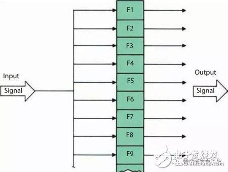
The received radar echo signal is subjected to Doppler frequency separation after passing through a set of parallel filters. Each filter is designed to obtain a narrow Doppler band as shown. Ideally, only each filter will produce an output when the frequency of the received signal falls within the corresponding frequency band;
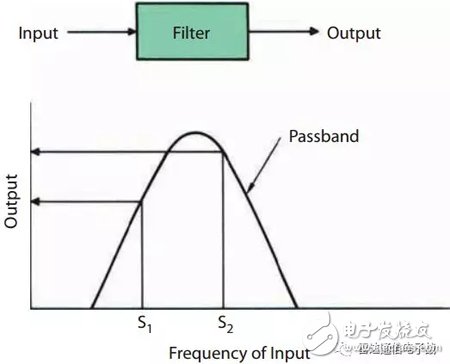
In fact, due to the filter side lobes, signal leakage may occur in adjacent frequency bands. If sorting is performed according to the distance/Doppler frequency, independent Doppler filtering processing is performed on each distance unit.
Each center frequency point of the Doppler filter bank is arranged in order from low to high. In order to minimize the signal-to-noise ratio loss when adjacent filters cross the target frequency, the passbands of the filter are always designed to cross each other. The form of the stack is as shown. Therefore, there may be leakage of adjacent frequency signals in areas where the filter banks overlap each other.

Under the condition of ignoring the filter side lobes, each filter can only pass the signal of a narrow band frequency. When the frequency of the signal is closer to the center frequency of the filter, the amplitude of the output signal is larger. In order to minimize the filter output energy loss, when the input signal frequency is between two adjacent filters, a method in which adjacent filter passbands overlap partially is employed.
Filter bandwidthThe selection characteristics of the narrowband filter are also exhibited over a sustained period of time; the bandwidth that can pass through the filter is primarily related to the accumulation time of the signal.
The sinusoidal signal (ie, the pulse waveform) has a spectral waveform as shown.
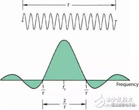
The relationship between filter bandwidth and accumulation time is somewhat different from the previously discussed method, namely:
· Keep the filter adjustment coefficient constant and continuously change the frequency of the input signal according to a certain step;
· The filter accumulation time is controlled within the accumulation time to ensure that the signal duration is at least the accumulation time.
Through the method described above, the response curve of the narrow-band filter at different frequency points is plotted by means of a graphical means. The central main lobe region of the narrowband filter is the passband of the filter, and the center frequency of the main lobe region is the filter resonance frequency. As shown, the two zero crossings of the filter spectrum have a bandwidth of 2 divided by the accumulation time.
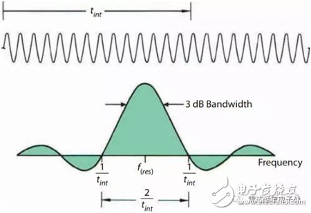
For ease of comparison, the dimensions of the above image in orientation are adjusted so that the zero width between the two looks the same. It should be remembered that the accumulation time is usually on the order of milliseconds, and the pulse width is approximately one thousandth of the accumulation time, on the order of microseconds.
Like the main lobe of the antenna radiation pattern, the 3dB bandwidth of the filter (ie, the width at which the output power is reduced to half the maximum) is more useful than the zero-to-zero bandwidth; similar to a uniform radiated antenna, the 3dB bandwidth is approximately zero. Half of the zero bandwidth. which is

In order to achieve the above bandwidth, the applied signal duration should be at least equal to the accumulation time. In practical applications, the filter bandwidth is typically determined based on the maximum available accumulation time.
If the waveform of the radar radiation is in the form of a pulse, a sufficient number of pulses must be accumulated to achieve a given signal bandwidth, from which it can be seen that the 3 dB bandwidth of the filter is equal to the PRF divided by the number of accumulated pulses. The bandwidth discussed above refers to the minimum achievable bandwidth. According to the actual engineering application, the filter passband will be broadened due to the loss caused by digital weighting.
Filter band passbandSufficient filters must be included throughout the bandwidth to estimate the range of Doppler frequencies to cover the target speed range of the intended design. For example, the maximum positive Doppler frequency is expected to be 100 kHz and the maximum negative Doppler frequency is -30 kHz. As shown in the figure below, the passband range of the filter bank is at least 100 + 30 = 130 kHz. Should be greater than 130kHz.
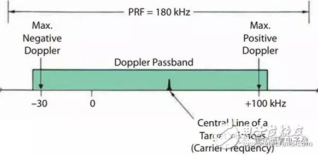
When the PRF is greater than the range covered by the maximum and minimum Doppler frequencies, the entire Doppler passband should be designed to be wide enough to ensure that all frequency components are able to pass.
On the other hand, if the PRF is smaller than the expected Doppler frequency spread range, the filter passband design value should be less than the PRF. This also proves the Nyquist theorem in another way, that is, the sampling frequency of any signal must reach twice the highest frequency of the signal to avoid blurring.
As shown in the figure below, when the PRF is smaller than the extended width of the Doppler frequency, the side Doppler line of the target Doppler will fall outside the passband. At this time, only the main Doppler main lobe line of the target Doppler can be filtered and output. .
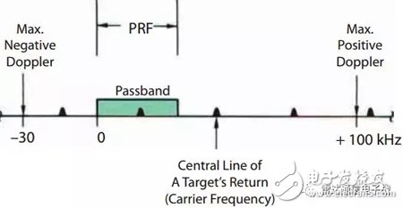
When the PRF is less than the Doppler frequency extension range, the filter bandwidth should be less than the PRF, thus ensuring that only one target signal is present in the passband.
The following figure depicts the relationship between the movement of the target line and the filter bank when the filter passband is equal to PRF. As can be seen from the figure, only one main spectrum of the target falls within the passband of the filter. Line; as the target Doppler frequency moves from low to high, the corresponding harmonic line is constantly changing.
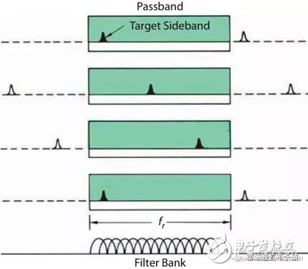
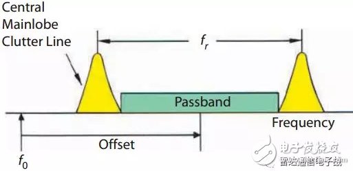
Generally, the passband width is set to be slightly smaller, thereby effectively avoiding ground clutter in the main lobe region, so that static clutter and moving targets can be separated. In practice, in order to simplify the design, it is not necessary to change the frequency of the Doppler filter, but to properly shift the spectrum of the radar echo relative to the filter bank.
Instruction Manual
1. Features
Clock display, 10 sets of adjustable timed power control, randomized power control, manual switch and optional DST setup.
2. First time charging
This Timer contains a rechargeable battery. It is normal that the new/old model runs out of battery if it wasn`t being charged for a long period of time. In this case, the screen will not turn on.
To charge : simply plug the timer to a power outlet. The charging time should take at least 15 minutes.
If the screen doesn`t light up or displays garbled characters, simply reboot the system by pressing the [RESET" button.
3. Set clock
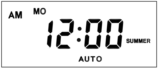
Hold [CLOCK" button and [WEEK" button to adjust week.
Hold [CLOCK" button and [HOUR" button to adjust hour.
Hold [CLOCK" button and [MINUTE" button to adjust minute.
Hold [CLOCK" button and [TIMER" button to select 12 hour/24 hour display.
Hold [CLOCK" button and [ON/AUTO/OFF" button to enable/disable DST (daylight-saving-time).
4. Set timer
Press [TIMER" button, select and set timer. Setting rotation : 1on, 1off, 2on, 2off, ...... , 10on, 10off.
Press [HOUR" button to set hour for timer.
Press [MIN" button to set minute for timer.
Press [WEEK" button to set weekday for timer. Multiple weekdays can be selected. ex: if selected [MO", the timer will only apply on every Monday; if selected [ MO, WE, FR", the timer will apply on every Monday, Wednesday and Friday.
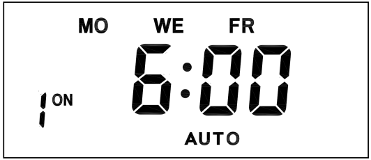
Press [RES/RCL" button to cancel the selected on or off timer. The screen will show "-- -- : -- --" , the timer is canceled.
Press [RES/RCL" button again to reactivate the timer.

When timers are set, press [CLOCK" to quit timer setting and return to clock.
5. Random function

Press [RANDOM" button to activate random function, press again to cancel function.
System only runs random function when [AUTO" is on.
Random function will automatically start the timer from 2 to 32 minutes after the setting.
ex : if timer 1on was set to 19:30 with the random function on, the timer will activate randomly between 19:33 to 20:03.
if timer 1off was set to 23:00 with the random function on, the timer will activate randomly between 23:02 to 23:32.
To avoid overlapping, make sure to leave a minimum of 31 minutes gap between different sets of timer.
6. Manual control
Displayed features:
ON : socket turns on.
OFF : socket turns off.
AUTO : socket turns on/off automatically via timer.
Manual ON setting
Press [ON/AUTO/OFF" button to switch from [AUTO" to [ON".
This mode allows socket of the device to power up. Power indicator will light up.
Manual OFF setting
Press [ON/AUTO/OFF" button to switch from [AUTO" to [OFF".
This mode turns socket of the device off. Power indicators will turn off.
7. Electrical parameters
Operating voltage : 230VAC
Battery : NiMh 1.2V
Power consumption : < 0.9W
Response time : 1 minute
Power output : 230VAC/16A/3680W
Q&A
Q: Why won`t my timer turn on?
A: It`s out of battery, you can charge the timer by plugging onto any power outlet. Charge the device for at least 15 minutes. Then press [RESET " button to reset the device.
Q: Can I set seconds of the timer?
A: No, the smallest time unit is minute.
Q: Does my timer keeps old settings without being plugged onto a power outlet?
A: Yes, the timer has an internal battery, it allows the timer to save settings without a power outlet.
Q: Is the battery rechargeable?
A: Yes, the battery is rechargeable. We recommend to charge it for 4 hours so the battery is fully charged.
Q: Does the timer needs internet connection?
A: The timer does not need internet.
Q: Does the screen have back light function?
A: It doesn`t support back light.
digital timer, digital timer socket, electronic timer socket, timer socket
NINGBO COWELL ELECTRONICS & TECHNOLOGY CO., LTD , https://www.cowellsocket.com