The life of a switching power supply is largely limited by electrolytic capacitors, which depend on the core temperature rise. This paper makes a comprehensive analysis of electrolytic capacitors from the aspects of ripple current calculation, ripple current measurement, electrolytic capacitor selection, temperature test method and life estimation.

The heat generated by the ripple current causes the internal temperature rise of the capacitor to accelerate the evaporation of the electrolyte. When the capacitance decreases by 20% or the loss angle increases to 2 to 3 times the initial value, the end of the life of the electrolytic capacitor is predicted. The lifetime of the capacitor can be predicted by examining the ripple current on the capacitor. In this paper, the output capacitance analysis of the flyback converter in continuous operation mode is taken as an example. The selection and life of electrolytic capacitors are comprehensively analyzed from the angle of ripple current.
1, ripple current calculation
Assuming a flyback converter with a continuous operating mode, the output current Io is 1.25A, the ripple rate r is 1.1, the duty ratio D is 0.62, and the switching frequency is 60 kHz, thereby calculating the secondary ripple current ΔIo and RMS current Io.rms.
Secondary ripple current ΔIo: 
RMS current Io.rms: 
Finally, the ripple current flowing through the output capacitor is obtained: 
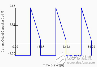
Figure 1 visually shows the ripple current waveform of the capacitor:

Figure 1 Ripple current waveform
2, electrolytic capacitor selection
From the above calculation and analysis, the ripple current flowing through the capacitor is 1.72A. Considering the volume and cost, an electrolytic capacitor with a ripple current of 1.655A is selected.
The ripple current needs to be selected at the power switching frequency. As shown in the figure below, the ripple current of a manufacturer's capacitance manual has a frequency factor, and the ripple current is different at different frequencies. The high-frequency low-resistance capacitor will give the ripple current at 100kHz. The design switching frequency is 60kHz, and the frequency factor is between 0.96~1. Take 1 here.

Figure 2 Capacitor ripple current frequency factor
Note: The ripple current also has a temperature coefficient, such as 105 ° C capacitor, the maximum allowable ripple current is about 1.73 times the rated maximum ripple current at 85 ° C ambient temperature. This parameter is generally not reflected in the capacitance manual.
3, ripple current measured
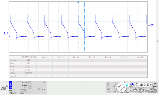
When testing the electrolytic capacitor ripple current, the capacitor pin needs to be inserted into the current probe, and the AC RMS can be read by the oscilloscope. The ripple current test results of this design example are shown in Figure 3. The oscilloscope reads the effective ripple current to 1.64A, which is close to the theoretical design. Therefore, theoretical calculations have greater engineering guiding significance.

Figure 3 measured capacitance ripple current
4, temperature test method
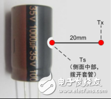
Measuring the surface temperature of the volume Ts: It needs to be carried out at the middle of the side of the capacitor. If the surface temperature of the capacitor is not uniform or unstable due to external influences, it is necessary to comprehensively measure the temperature of the surface of the capacitor at 4 points, and then take the average value.
Measuring ambient temperature Tx: The thermocouple should be placed about 20 mm away from the surface of the aluminum shell. If the space is insufficient, keep a minimum distance of 10 mm. If the ambient temperature is not uniform or unstable due to external influences, comprehensive measurement is required. The temperature above the point is taken and the average is taken.

Figure 4 Ambient temperature and surface temperature measurement
5, electrolytic capacitor life estimation
In this design, the selected electrolytic capacitor is a high-frequency low-resistance electrolytic capacitor with a ripple current of -40 to 105 ° C, 5000 hours, and 1.655 A. The highest measured ambient temperature Tx is 80 ° C, and the surface temperature Ts of the casing is 85 ° C. Then the life expectancy is estimated as follows.
(1) Estimate the actual core temperature rise: 
among them:
△To is the allowable core temperature rise for To, that is, the temperature rise of the capacitor core at the rated ripple current. The 105°C capacitor △To of this selection is 5°C, which can be obtained from the original factory or industry data;
â–³Tx is the actual core temperature rise;
Ix is the actual ripple current of 1.64A;
Io is rated ripple current 1.655A.
(2) Estimating the life of the capacitor:

among them:
Lo is rated for 5000 hours;
To is the highest rated working environment temperature of 105 ° C;
Tx is the actual ambient temperature of 80 °C.
When Tx is not easily available due to environmental factors, Ts can be used instead, which can further provide safety margin to ensure product life.
KNB6-40 Miniature Circuit Breaker
KNB6-40 Mini Circuit breakers, also named as the air switch which have a short for arc extinguishing device. It is a switch role, and also is a automatic protection of low-voltage electrical distribution. Its role is equivalent to the combination of switch. Fuse. Thermal Relay and other electrical components. It mainly used for short circuit and overload protection. Generally, According to the poles, mini Circuit breaker can be divided into 1P , 1P+N , 2P, 3P and 4P.
KNB6-40 Miniature Circuit Breaker,Electronics Miniature Circuits Breaker,Automatic Miniature Circuit Breaker,Mini Circuit Breaker
Wenzhou Korlen Electric Appliances Co., Ltd. , https://www.korlen-electric.com