Abstract: Based on the 8th “Freescale†Cup National College Student Smart Car Competition, this design proposes a scheme to guide the vertical car tracking according to the linear CCD image acquisition. This paper introduces the basic idea of ​​this scheme, the physical principles on which it is based, and focuses on the optimization of steering and obstacle problems under the dual speed control algorithm, and the actual production of the car according to the scheme. Practice has proved that the program is feasible and the effect is better.
This article refers to the address: http://
Keywords: smart car; upright; speed control; Kinetis K10; TSL1401CL
introduction
In the past, smart car races were divided into photoelectric groups, camera groups and electromagnetic groups. In this competition, the photoelectric group first tried the trolley to walk upright, and for the first time used a linear CCD as an image acquisition sensor. This article introduces the Freescale Kinetis K10 as the main control chip, how to use the image acquired by the linear CCD for data processing and based on the original dual speed control algorithm, solves the problem of smart car over obstacles from the speed control.
1 Design principle
1.1 Data Acquisition Algorithm
The detection path parameters can use a variety of sensor components, such as photocell arrays, CCD image sensors, laser scanners, and the like. Various detection methods have corresponding advantages and disadvantages, and the most commonly used methods are photocell arrays and CCD image sensors. How to effectively use the internal resources of the microcontroller to detect the path parameters is the key to determine the detection scheme.
The CCD sensor is a new type of photoelectric conversion device that stores signal charges generated by light. When a pulse of a specific timing is applied to it, the stored signal charge can be self-scanned by directional transmission in the CCD. The CCD has an area array and a line array, and the area array is a device in which CCD pixels are arranged in one plane; and a line array is a device in which CCD pixels are arranged in a straight line. A linear CCD is used in this design as an image sensing element.
In this design, the TSL1401CL linear CCD is used. The TSL1401CL linear sensor array consists of a 128×1 photodiode array, associated charge amplifier circuit and an internal pixel data holder. The array consisted of 128 pixels, each of which had a photosensitive area of ​​3 524.3 μm 2 and an interval between pixels of 8 μm. The chip is simple to operate and requires only one serial input signal and one clock signal for data reading.
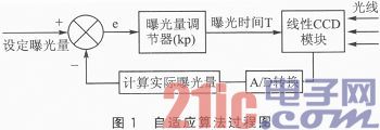
In the CCD acquisition, the exposure time adaptive strategy used is shown in Figure 1.

As can be seen from Figure 1, the exposure time adaptive strategy is a typical closed-loop control, the control object is the exposure time of the linear CCD module, and the feedback is the exposure amount induced by the linear CCD. The goal of the adjustment is to set the exposure. The working principle of the controller is to subtract the actual exposure amount from the set exposure amount. The difference is the deviation e of the exposure amount. The exposure amount adjuster uses Kp multiplied by e plus the last exposure time as the new exposure time. Exposure, exposure time adjustment directly affects the actual feedback exposure, so repeated adjustments can achieve the purpose of adapting to ambient light. Our approach is to take the average value of the 128 pixel voltages collected as the exposure amount equivalent, and the set exposure amount is also the set average voltage of 128 pixels.
1.2 Data Processing Algorithm
In image processing, the edge detection method is used to detect the track. Because the image voltage values ​​of the track are different, the groove of the image appears at the intersection of the white track and the edge of the black track, that is, the falling edge of the image value. The 128 image points of the CCD are labeled with coordinates, and from 0 to 127, the left and right values ​​of the black lines on both sides can be determined.
The left and right coordinates are obtained, and according to the formula "neutral line = (left coordinate + right coordinate) / 2", the center line is extracted. Of course, we must also consider the situation of edge loss. We adopt the strategy of patching. If the coordinates are lost at this time, we will use the coordinates that have not been lost at the previous moment, so that it can be realized in the cross, straight, curved or dotted lines. Good identification and control to adapt to a variety of different track requirements.
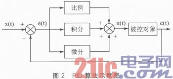
For the control of the motor, the traditional PID control algorithm is adopted. PID control is one of the earliest development strategies. The PID controller integrates information about the past (I), present (P) and future (D) aspects of the system, and the control effect is satisfactory. More than 95% of industrial control adopts PID structure, which has the advantages of simplicity, robustness and high reliability.
The schematic diagram of the PID algorithm is shown in Figure 2.

Among them, the formula of the digital PID algorithm used is as follows:
In summary, the traditional digital PID algorithm or the improved intelligent PID algorithm is adopted in the closed loop part of the trolley control system.
2 Dual speed control algorithm design
2.1 Traditional speed control algorithm
Since the entire driving process of the car model is constantly changing, the response to the system is very fast when the track structure is complicated and the running speed of the car model is high. Therefore, speed control must be fast, accurate, and responsive. Known by the PID principle: the hysteresis effect of I (integral term) will make the control system slow down. Therefore, in order to adapt to various types of tracks under the high-speed operation of the vertical model, the PI control recommended in the official design scheme is abandoned. Faster, faster adjustment of PD control.
The upright model is a dual motor that controls the left and right wheels separately, and turns through the differential speed of the left and right wheels. In the motor control of the upright car, the output of the PWM wave is composed of the upright control amount, the speed control amount and the steering control amount, namely:
Motor output = upright control + speed control + steering control (1)
The control formula in the traditional speed control algorithm is:
Speed ​​control amount = speed set value = speed measurement value = speed set value - (revolving wheel speed + right wheel speed) / 2 (2)
As can be seen from the above equation, the actual value is the average of the left and right wheel speeds. The speed control amount is added to the left and right motors at the same time, that is, the left and right motor speed control amounts are always the same, so that the left and right motor speed control amounts are always the same. Under the traditional speed control algorithm, the steering control amount is equivalent to a disturbance amount with respect to the speed control amount.
2.2 Dual speed control algorithm
The idea of ​​dual speed control we designed is as follows:
Left motor output = upright control + left wheel speed control + steering control (3)
Right motor output = upright control + right wheel speed control - steering control (4)
Because the car stays upright during the driving of the car, the erect value is a fixed value when the car is in an upright position, so:
Left speed control amount = no fixed value - left wheel speed measurement value (5)
Right speed control amount = set value - right wheel speed measurement value (6)
The left and right wheel speed values ​​are both given by the wheel speed control amount and the steering control amount.
This shows that:
Left wheel speed control amount = set value - (speed control amount measurement value + steering control amount measurement value)
Right wheel speed control amount = set value - (speed control amount measurement value + steering control amount measurement value)
In fact, the steering control amount is a part of the speed control closed loop. When the C language is implemented, the two control quantities are calculated by the same control algorithm. The final output is:
Motor output = upright control + speed and steering control
It can be seen from the principle that when driving on a straight road, since the steering control amount is close to zero, the conventional speed control is the same as the speed output under the dual speed control we use. When turning, the PID control after the image acquisition generates the turning control amount, forming the left and right wheel differential speed, and realizing the turning of the car model. In the traditional speed control mode, the amount of turning control is not adjusted by the speed control. The turning amount is a kind of disturbance amount relative to the speed control parameter. Under the double speed control algorithm, the turning amount is affected by the current tire speed, so it is affected by the round. Speed ​​control adjustment. Under the dual speed control, when the car model runs, the double speed control will actually slow down the car model into the bending control speed and speed up the car model exit control speed. In the experimental effect, the double speed control slows down the amount of control of the car into the corner, which greatly reduces the side slip and rollover caused by the rapid bending of the car model, and the quick adjustment of the exit bend enables the car model to Adjust the position of the car model more quickly after exiting the corner, which is convenient for handling special curves such as continuous corners and obstacles, dotted lines and starting lines after exiting. Therefore, under the dual speed control, the speed control amount during the turn is not zero, which is equivalent to the existence of the speed closed loop when the system turns, and the left and right differential speed of the wheel is controlled by the speed closed loop.
3 experimental data
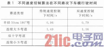
The following is the shortest time that the measured system can pass under different road conditions under various road conditions. The timing is measured by the photoelectric gate, as listed in Table 1.

It can be seen from the above data that the more the curve is, the more obvious the speed increase brought by the double speed control, and the increase caused by the continuous small S curve is not large.
In this smart car competition, for the photoelectric balance car, the test of the biggest speed increase is the obstacle part of the smart car for the first time. The biggest difficulty in the obstacle part is that when the car model is in an upright state, it is unpredictable whether the left or right wheel of the car model passes through the obstacle first. When the car model passes through the obstacle at high speed, there will be a phenomenon that the car model is vacant and the car model motor stalls. When the motor stalls, it is uncontrollable which of the left and right wheels will land first when the car model is landing. Therefore, the speed of the car model returning to the ground is uncontrollable, causing the car to fall to the ground or roll over.
The dual speed control can greatly reduce the stall of the car model when it passes the obstacle. When the car model passes the obstacle, whether the left or right wheel passes the obstacle first, the wheel stalls and the double speed control, the speed control of the dual motor is independent, and because the control of the motor adopts the PD control with fast adjustment speed, it can be controlled. The motor quickly adjusts the body posture after the stall returns to the ground, and passes through a single obstacle at a high speed with a low center of gravity. After repeated trials, the dual speed control under PD control can well overcome the influence of the car model on the car model when the obstacle is over, and the effect is very good.
Conclusion
In this competition, the organizing committee requested the photoelectric group to stand upright for the first time. This design is based on the Freescale K10 chip and is the first attempt to use a linear CCD as an image processing sensor. According to the image taken by the linear CCD, through the principle of PID control, the dual-speed control algorithm is used to achieve better processing of highly complex road conditions and obstacles, and the effect is good.
Pa System Speaker ,Speaker Audio System,Dj Sound System,Stage Equipment System
NINGBO RFUN AUDIO TECHNOLOGY CO.,LTD , https://www.mosensound.com