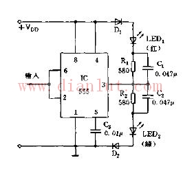
Using the trigger end (2 feet) of the 555 circuit and the set and reset characteristics of the threshold end, a test pen can be formed to detect whether the state of the digital logic is normal, as shown in the figure.
When the probe input is low level “0â€, LED2 (green) is on; when the high level “1†is input, LED1 (red) is on. The R1C1 and R2C2 networks are acceleration networks.
The logic pen is suitable for testing digital circuits such as TTL and MOS, and VDD is optional within 5 to 15V.

Shaded Pole Motor,Capacitor Motor Yc Series,Capacitor Motor Tl61,Shaded Pole Ac Motor
Wentelon Micro-Motor Co.,Ltd. , https://www.wentelon.com