Introduction to the principle of optical fiber, optical fiber is referred to as optical fiber or optical fiber, and optical signal transmission is performed by using the light guiding property of the material.
Optical fiber communication: The general communication medium can be divided into three bandwidths according to its speed, that is, narrow-band transmission (data transmission speed is between 45 and 150 bps, such as telegraph and teletype typing, etc. .), language-level transmission (data transmission speed between 300 and 9600 bps, such as general telephone line communication) and broadband transmission (data transmission speed 19200 bps to 500000 bps or above), for broadband transmission, Its communication medium is commonly used in coaxial cable, fiber optic cable and microwave. The application of optical fiber in communication is in the position of tomorrow's star. One of the optical cables can replace more than 10,000 telephone lines. Optical fiber is an excellent tool for transmitting signals. With a slender light core, you can do a lot of communication work.

Figure 1-1-1 Light pipe signal transmission
Humans have long known to use light to transmit signals, and electricity communication is actually only a hundred years old. In 1870, John Tyndal used water column as an optical medium experiment, and some people proposed the concept of light pipe (Figure 1-1-1). The light signal is transmitted inside the iron pipe, taking into account the problem of scattering of the light signal, so at a certain distance, the diffused beam is concentrated by a lens in the iron pipe to reduce the loss of the light signal (Figure 1-1- 1)). In 1930, attempts were made to use glass fiber to transmit light. Chinese scientist Dr. Gao Wei proposed the concept of fiber-optic communication in 1966. Then Corning completed the loss of fiber with a loss of less than 20 dB per kilometer in 1970. Bell Labs of the American telegraph company published chemical vapor deposition (MCVD) in 1974. The optical fiber manufacturing technology, the commercial optical fiber communication system began small-scale testing in 1980, and the competition was adopted by countries in three years. In order to meet the information age, the world's major telephone companies are actively expanding the optical fiber communication network. Currently, The transmission of optical signals has generally changed to the technology of fiber optic cables. Fiber optic technology can be applied to long-distance, high-multitasking network signals or telecommunications signals. At this point, the overall performance of the transmission quality of the optical signal and the effective distance that can be transmitted is greatly improved. At present, China is also laying optical fiber in long-distance telecommunications channels. Although the popularity is limited to the mainline network, the price of optical fiber is getting lower and lower, and the cost of optical fiber communication components and construction is greatly reduced. Therefore, the entire island fiber-optic and optical fiber feeder network will be in the future. (Fiber To The Feeder-FTTF), Fiber To The Neighborhood (FTTN), Fiber To The Building (FTTB), Fiber To The Desktop (FTTD), Fiber to Home ( FTTH-Fiber To The Home), on-demand video, is also the direct deployment of fiber to each user's home, and is also the best way to promote multimedia to users, which will be foreseeable, the vision of fiber transmission can be imagined It will be very embarrassing.
As for fiber optics, the HFC-Hybrid Fiber Coaxial is the most commonly used on cable television networks, and optical fibers are used to transmit high-quality signals from the head end of the coaxial cable to optical nodes or distribution centers. The hybrid fiber-optic coaxial network combines the characteristics of fiber and coaxial. The optical signal is converted into an electrical signal by an optical modem at the optical node, and then distributed to individual users through a short-distance coaxial tree network; The return signal of individual users is also collected, and transmitted back to the head end to convert the electrical signal back into an optical signal, which is output by the laser transmitter.
Fiber Optic Sensor
The so-called optical fiber sensor uses the optical fiber to transmit the measured signal. Under normal circumstances, the fiber faithful transmission measurement signal changes because the optical fiber characteristics are easily affected by the environmental factors to be tested. Sometimes we can also use this feature. This modulates the signal measured by the fiber. Fiber optic sensors have several advantages as follows:
1. High sensitivity.
2. Without interference from electromagnetic noise, the signal is transmitted quickly.
3. Small size, light weight, long life and low price.
4. Suitable for work in special environments. It has the advantages of insulation, high pressure resistance, high temperature resistance and corrosion resistance.
5. The geometry of the optical arrangement is flexible and can be adjusted according to environmental requirements.
The detection of the fiber sensor signal has two modes: light intensity type and phase interference type. The main principle of the light intensity type is to modulate the signal strength by using changes in geometric physical quantities for use in fields such as pressure, stress, acceleration, sound waves, rotational speed, temperature, magnetic field, voltage, electric field, and the like. Although the sensitivity is lower than that of the phase interference type, the structure and principle are very simple, the operation is convenient, and the advantage of the lower-cost optical fiber can be adopted.
1-1-3 Construction and Classification of Optical Fibers
Optical fibers can be classified according to their structure (Fig. 1-1-3-1):
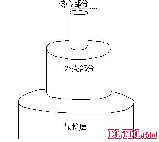
Figure 1-1-3-1 Construction of optical fiber
1. The part of the optical fiber that transmits the optical signal. The general fiber core material is quartz glass and plastic (Plastic Optic Fiber-POF). The price of the plastic fiber is about one tenth of that of the quartz fiber, and the core diameter of the quartz fiber ( The core diameter is small, the quartz single mode fiber is about 5~12μm, the quartz multimode fiber is about 50~150μm, and the plastic fiber has a core diameter of about 1000μm.
2. Cladding: that is, the part that is covered on the periphery of the core, the light is reflected and refracted when it is incident on two different media. With total reflection, we can easily use the fiber to change the direction of light travel, and During the process, the loss of light is minimal. In order for light to travel through the core, the light travels in a totally reflective manner, so the refractive index of the core must be greater than the refractive index of the outer casing. In addition, if we want light to be totally reflected when the core is incident on the outer casing medium, then the incident angle of the light when it enters the fiber can not be too large, as shown in Figure 1-1-2-2, assuming an interface When the incident angle θm of the incident light fiber is incident, the critical phenomenon of total reflection occurs when the medium is incident on the outer casing, that is, the angle of refraction of the two rays at the interface is 90 degrees, and the incident angle of the two rays at the interface is θc, and the incident angle of the light at the interface is as When it is greater than θm, the light will not be transmitted in the core.
Set the core refractive index n1
Refractive index of the outer casing n2
At the interface, a light refraction angle θ2
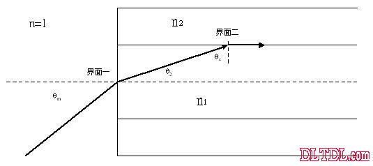
Figure 1-1-3-2 Critical phenomenon of total reflection occurring when entering the outer casing medium
At interface one, according to the law of refraction
N1 sin θ2 = sin θm
In interface two, according to the law of refraction
N2 sin90°= n1 sinθc
Also, θ2 = 90°-θc
Available
N2= n1 cosθ2 , cos2 = n2 / n1
Sin θ2 = ( 1- cos2θ2 ) 1/2
=( n12- n22 )1/2 / n1
Sin θm = n1 sin θ2 = ( n12- n22 ) 1/2
Usually define the numerical aperture (Norical aperture) NA = ( n1- n2 ) 1/2
3. The protective layer (Jacket) is protected around the outer casing to prevent damage to the outer casing and core of the optical fiber.
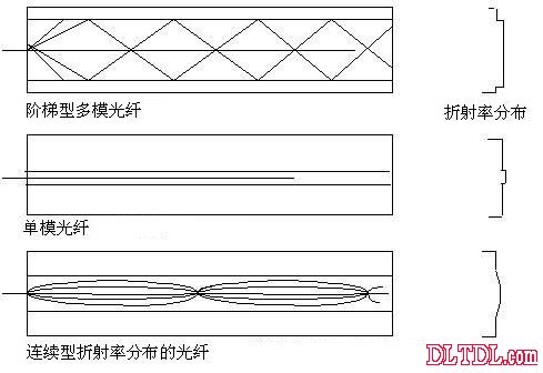
Figure 1-1-3-3 The refractive index distribution of the fiber
Optical fibers can be classified according to their refractive index distribution and characteristics (Fig. 1-1-3-3-3):
1. A multi-mode fiber of a step-type refractive index distribution: or a ladder-type fiber, whose refractive index of the core of the fiber and the outer casing changes abruptly. The stepped multimode fiber usually has a difference in the arrival time of the light parallel to the central axis and the arrival time of the curved fiber. As shown in Figure 1-1-3-4, the transmitted signal is transmitted over a long distance or has distortion distortion. There is also a phenomenon in which the signal is widened, and the dispersion distortion of the waveform is large, so that the phase information in the measurement signal cannot be transmitted. If a multimode fiber is used as the fiber sensing, it is generally only modulated in terms of luminance (amplitude). Multimode fiber is usually available in diameters from 50 to 1000 μm, and is inexpensive and easy to use. However, the signal transmission bandwidth is narrow and cannot be used for long-distance transmission.
The modal number M of the multimode fiber of the stepped refractive index profile can be obtained by the following formula:
Among them, the core refractive index n1
Refractive index of the outer casing n2
Core radius a
Wavelength of light λ
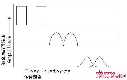
Figure 1-1-3-4 The signal transmitted by the stepped multimode fiber is transmitted over long distances or has distortion distortion
It can be seen from the above that to reduce the modal number M of the multimode fiber with a stepped refractive index profile, the value of NA or n12-n22 can be reduced, but this will affect the amount of light coupled into the fiber, and secondly increase the wavelength of light λ. Or to reduce the radius a of the core, that is, to form a so-called single mode fiber.
2. Multimode fiber with continuous refractive index profile:
Generally, a continuous refractive index distribution fiber (or oblique fiber) can have a response frequency of up to 800 MHz/km and is expensive, so it is suitable for some higher-level applications. The refractive index distribution of a continuous refractive index distribution fiber is as follows: the closer to the center, the smaller the refractive index. Therefore, the path in which the light travels inside is a curved shape. The path of the path traveled by light within the fiber is related to the gradient of the refractive index profile. Some of the plastic optical fibers use a step-type refractive index distribution called SI-POF, and some use a continuous refractive index distribution called GI-POF to achieve a Gb/s transmission rate, not only a high transmission bandwidth. It is quite cheap in terms of price, so it has great potential for short-range communication.
3. Single-mode fiber: The single-mode fiber has a step-like change in the refractive index of the fiber core and the outer casing. The core diameter is particularly small (5-12 μm), allowing only one beam of light to enter the core, thus enabling the phase information of the optical signal. Only its core is small, so it is troublesome in terms of beam coupling.
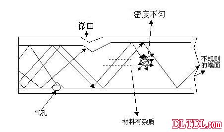
Figure 1-2-1 Causes of fiber loss
1-2 Signal loss and distortion of optical fiber
When talking about optical fiber transmission optical signals, we must first talk about the loss and distortion of optical fiber signals. The materials of optical fibers can be divided into inorganic materials and organic materials. Organic materials such as PMMA, PC, PS or PCF plastics, and PMMA transparency. The best use rate is the highest, but its loss is larger than that of inorganic materials. The transmission loss of plastic fiber at 150nm wavelength is 150dB/km, while the loss of quartz glass fiber is 0.2dB/km, but the price is lower, mostly used for close range. Communication, and inorganic materials, the current loss of quartz glass is the lowest, and has high strength and good stability, its main component is silicon dioxide (SiO2), when it is to increase the refractive index, it will add two Materials such as cerium oxide, aluminum oxide, dioxide, and phosphorus oxide are considered to be added with materials such as boron trioxide and fluorine in order to reduce the refractive index thereof. In addition, plastic optical fibers are currently far less heat resistant than quartz glass fibers, and transmission losses increase at temperatures above 80 °C.
It is discussed in the following terms:
1. Absorption loss of materials:
The reason for the absorption loss of the material is that the fiber contains transition metal elements (such as Sc, Ti, V, Cr, Mn, etc.), and such metals have a broad absorption band in the spectral range. In addition, the defects of the hydroxide ions and materials (such as small bubbles generated inside the fiber manufacturing) also cause absorption loss, and these factors have been greatly improved in manufacturing technology.
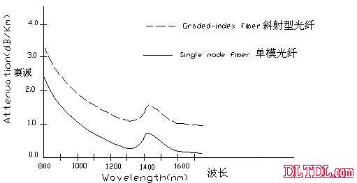
Figure 1-2-2 Generally, the choice of fiber is 1300nm or 1500nm wavelength as the ideal light source.
2. Scattering loss of material:
Rayleigh scattering occurs due to the density or composition of the material. The loss value is inversely proportional to the fourth power of the wavelength, as shown in Figure 1-2-2. Therefore, the longer the wavelength, the smaller the loss, so the ideal choice is 1300nm. Or the 1500nm wavelength is used as the light source. In addition to Rayleigh scattering, there are other scattering behaviors, but the effect is not as great as Rayleigh scattering.
3. Loss caused by mechanical deformation:
When the micro-curve and the bending caused by the mechanical deformation cause the loss of the signal transmitted by the optical fiber, the so-called micro-bending loss means that when the optical fiber is wound on a cylindrical shape, the unevenness of the surface of the cylinder causes a micro-curvature phenomenon. The uneven side pressure received causes a slight final bending in the axial direction, thus causing a loss. The so-called bending loss refers to the loss caused by the light being refracted to the outside when the incident angle is smaller than the critical angle.
4. Dispersion and distortion of fiber optic signals
The distortion of the fiber signal is mainly caused by the dispersion, that is, the fiber has different refractive indices for different wavelengths of light. For the light source, the typical infrared light-emitting diode IR LED has a wavelength of 880 nm and a wavelength bandwidth of 40 nm. That is, the wavelength range is from 860 nm to 900 nm. As the wavelength range of the laser diode is only 2 nm, the dispersion problem is much smaller. As shown in Figure 1-2-3, the longer the wavelength of light, the smaller the refractive index of the material of the fiber, which also results in Figure 1-2-4.
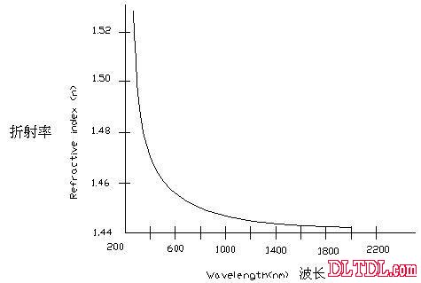
Figure 1-2-3 The longer the wavelength of light, the smaller the refractive index of the material of the fiber
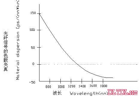
Figure 1-2-4 Dispersion distortion of fiber signal
1-3 fiber optic communication components
The optical fiber communication device includes an optical conversion interface, a fiber optic communication transmitter component, a receiving end component, an OTDR-Optical Time Domain Reflector, an optical fiber monitoring system, a fiber fusion splicer, and a fiber cutting device. And so on. Optical fiber communication components are generally divided into two categories according to the operational type: active components and passive components. The domestic fiber optic communication industry began with the focus on manufacturing optical cables, optical connectors, optical pre-forms and spinning, and slowly entered the field of active components such as optical transceiver modules and fiber amplifiers.
1-3-1 Optical fiber communication active and passive components
Active component refers to a component that can perform energy conversion, that is, components such as diodes, transistors, vacuum tubes, POWER ICs, TV CRTs, LED displays, liquid crystal displays, plasma display PDPs, etc. The function of signal conversion or amplification, fiber optic communication active components can be used for electrical conversion, optical conversion or amplification of light, such as optical transmitters, optical receivers, optical amplifiers, generally have two different designs of analog and digital.
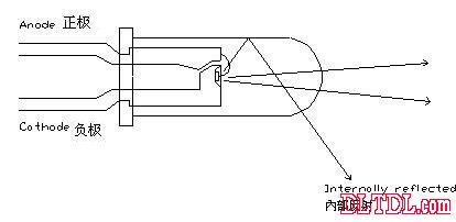
Figure 3-3-1-1 LED
The lens of the light-emitting diode for communication is generally used for focusing, and the angle of view of the up, down, left, and right directions can be changed to an appropriate incident angle, as shown in Fig. 3-3-1-1, but the reflected light of the mirror walls on both sides causes both sides. The light field forms an ineffective circular projection.
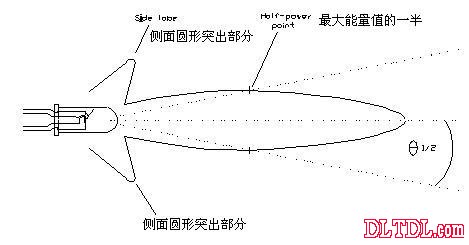
Figure 3-3-1-2 LED illumination angle
The light field of the LED is elliptical, and its illumination angle, as shown in Figure 3-3-1-2, is the envelope line formed by all the points of half the maximum energy value in the light field, and then find the longest section in the envelope line. The line is then connected to the end point of the longest line in the envelope line by the center point to determine the angle of illumination. The semiconductor laser also uses this definition. There is a so-called "full width of half the maximum energy value". Full Width at Half Maximum (FWHM) is used to define the beam diameter of a semiconductor laser. The FWHM is twice the distance from the highest brightness to the highest brightness in the laser beam. Therefore, the FWHM must first find the brightest of the entire laser beam. Position, then scan to the right until you find the one-half brightness and record the position here, use the same method to scan to the left, record the position here, subtract the two positions, and then calculate the horizontal direction FWHM. The same method scans up and down, and you can also find the vertical FWHM.
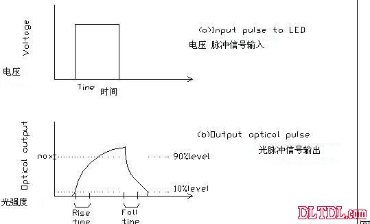
Figure 3-3-1-3 LED response
The response of the light-emitting diode (LED) for communication (Fig. 3-3-1-3) is highly reliable, and the ratio of light coupling into the fiber is large. The semiconductor laser has a large optical power and modulation speed for feeding into the optical fiber, so it is suitable for high-speed transmission. In order to increase the percentage of light-coupled light-coupled into the fiber, it is necessary to select a product with a small light-emitting angle. Generally, the point-source light-emitting diode coupling percentage is better than that of the large-surface light source (the coupling condition is shown in Figure 3-3-1-4). ).
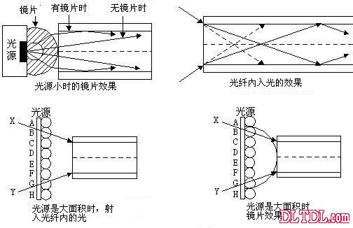
Figure 3-3-1-4 LED and fiber coupling
Generally, electronic passive components such as wound type variable resistors, carbon film type resistors, metal film fixed resistors, die resistors, array resistors, paper media, and the like. A passive component of a fiber-optic communication refers to a component that exhibits only static characteristics, that is, a component that does not require additional energy to function. That is to say, the transmission of light is passed, separated, turned or attenuated purely, without involving the conversion and amplification of light energy and electrical energy. Fiber optic passive components can be broadly classified into: optical fibers and optical cables that transmit optical energy, optical fiber connectors and patch cords that connect optical energy, fiber attenuators that attenuate optical energy, optical reflectors that reflect light energy, and splitter splitters/fiber couplings. , fiber-optic wavelength multiplexer, optical isolators that isolate reflected light, optical circulators and fiber switches that change optical paths, and polarizers that polarize.
1-3-2 Cable Manufacturing and Connection
The manufacturing process of the optical cable can be roughly divided into four steps: fiber manufacturing, core manufacturing, concentration, and outer skin. In order to control the refractive index, in order to control the refractive index, an oxide such as phosphorus or ruthenium is often added to the quartz fiber, and the preform is formed by chemical vapor deposition, and then heated to 2000 degrees Celsius or more, softened, elongated, and then drawn. The method produces a core, and the spinning speed is about ten to several tens of meters per minute. . The preform having a diameter of 2 to 3 cm and a length of several tens of meters can be made into tens of kilometers of optical fibers having a diameter of about 0.12 mm. The fiber after spinning is covered with a double-layer plastic film, and a poly-resin is added as a buffer layer between the two-layer coating. The primary coating material is epoxy resin, silicon, urethane, etc., and the secondary coating is nylon. Polyethylene, etc., the outer skin is made of polyethylene or PVC. The plastic optical fiber is made of high-purity resin as a core material, and the outer skin is covered with a special fluorine resin.
The discontinuity of quartz glass fiber is not as easy as the wire. There are two ways to connect the fiber. One is the movable connection, which is the connection method that can be removed and the second is the permanent connection (joint or splice, as shown in Figure 13). 2-2-1). Regardless of the type of connection, it is preferable to have no gap in the core part of the two fibers, and should be vertically connected along the axial direction, and the dimensional accuracy is very high. When considering cutting the optical fiber, a dedicated optical fiber should also be used. The thread cutter and the fiber stripper work.
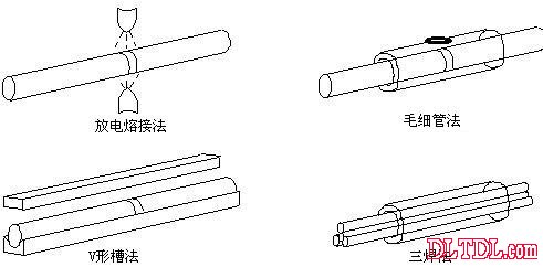
Figure 13-2-2-1 Permanent fiber connection
There are roughly four types of permanent connections:
Discharge welding method
The quartz is melt-bonded by high voltage discharge. The quartz contacts at both ends of the joint must be coupled to the front side.
2. Capillary method
The two fibers to be joined are wrapped by a hollow tube having a larger diameter and a larger diameter than the optical fiber, and then fixed by an adhesive. The diameter of the hollow tube is just enough for the fiber to be nested. If it is too large, the two fibers are poorly coupled.
3.V-groove method
The two sections of the optical fiber are placed by the V-shaped groove, and then the adhesive is fixed by the adhesive.
4. Three-bar method
Firstly, the two fibers are clamped by three rods and then inserted into the through-tube, and heated outside the tube to be fixed and fixed.
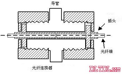
Figure 1-3-2-2 Fiber Connector
Connector connections are used in applications such as connectors or photodetectors. For example, when the connector is connected to two sections of fiber, it can be disassembled for correction or maintenance when necessary. When connecting with a connector, care should be taken to fix the center of the fiber in the center of the plug (Figure 1-3-2-2) to form an optimal coupling state.
When the optical fiber is incident on the diode laser, the reflected light spot is often reflected back into the resonant cavity of the diode laser, causing the noise of the laser light output. This situation can be improved by using an optically isolated pigtail. Works with fiber optic connector sets in optically isolated connectors. As for plastic optical fibers, it is easier to combine or align light than quartz glass fibers. Therefore, when light is received and received, the light time is shorter and the difficulty is lower. In addition, the core diameter of the plastic optical fiber is larger than that of the quartz optical fiber, so the design and manufacture of the connecting fixture of the optical fiber end is relatively simple, and the relative cost is also low.
1-4 Other applications of optical fiber
1-4-1 fiber bundle light guiding illumination
In addition to communication, optical fiber can also be applied to sensing, lighting, decoration, and signing. The application range is very wide. It is a high-tech field in sensing and communication, while the symbol, decoration and lighting are focused on people's livelihood. Generally, fiber-optic beam guiding illumination, fiber optic marking, decoration and lighting can be used for architectural lighting decoration, advertising effect application, industrial sign lighting, underwater lighting decoration, special landscape lighting decoration. The advantages are as follows:
1. It has light transmission, small transmission loss, no power supply at the end point, no heat generated by cold light, and good safety.
2. Easy processing, excellent durability and maintenance, good weather resistance and waterproof.
3. It can filter infrared and ultraviolet rays, protect your eyes or protect the illuminated body.
4. The light source saves power.
The most direct and most visible example of a fiber optic mass transmission optical signal is the Fiberscope, which uses a bundle of neatly bundled fiber ends to transmit images, usually with an objective lens attached to one end of the fiber bundle. The other end face is attached to the eyepiece to form a measuring device that can directly observe the minute object.
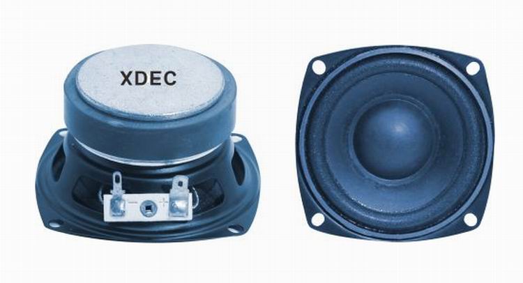
Woofer:
Speakers with working frequency response range from 150~500Hz are called woofers.
FAQ
Q1. What is the MOQ?
XDEC: 2000pcs for one model.
Q2. What is the delivery lead time?
XDEC: 15 days for normal orders, 10 days for urgent orders.
Q3. What are the payment methods?
XDEC: T/T, PayPal, Western Union, Money Gram.
Q4. Can you offer samples for testing?
XDEC: Yes, we offer free samples.
Q5. How soon can you send samples?
XDEC: We can send samples in 3-5 days.
Woofer Speaker,Home Theatre Woofer,Audio Woofer,Sound Woofer
Shenzhen Xuanda Electronics Co., Ltd. , https://www.xdecspeaker.com