This article selects the MSP430G2231 as the launchpad core board microcontroller, using the Launchpad core board and the baseboard form, to control the stepper motor. Slippage, the sliding rheostat, is used to control the speed of the motor. There are two toggle buttons in the system. One toggle button is used to select the mode of the stepper motor, such as four-phase or four-phase, and the other dial. Buttons are used to control the direction of rotation. The digital tube can be used to display the mode and direction, as well as the percentage of speed.
Overall system design diagram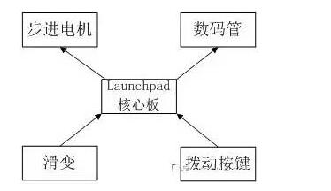
In the hardware design, only the peripheral circuits need to be designed to leave the interface with the Launchpad core board, which saves design time and saves costs, and eliminates the need to purchase additional simulators, thereby minimizing design costs.
In terms of software design, it can make full use of various functional modules of the G2 series microcontrollers, such as clock systems, TA timers, ADC10 analog-to-digital converters, watchdogs, and IO port interrupts to design high-efficiency, low-power consumption, Compact and powerful product.
Development of MSP430G2 Series Launchpad Development Board and Hardware Resources
MSP430G2 Series Launchpad is a low-cost development platform introduced by TI. It is suitable for use with TI's latest MSP430G2xx family, and its USB-based integrated simulator provides all the hardware and software necessary to develop applications for the full range of MSP430G2xx devices.
The LaunchPad has an integrated DIP target socket that supports up to 20 pins, allowing the MSP430 Value Line device to be easily plugged into the LaunchPad board.
In addition, it provides on-board Flash simulation tools for direct connection to a PC for easy programming, debugging, and evaluation. The LaunchPad Experimenter Board can also program the eZ430-RF2500T target board and the eZ430-Chronos watch module eZ430-F2012T/F2013T target board. In addition, it provides a 9600-baud UART serial connection from the MSP430G2xx device to the host PC or connected target board. In fact, the physical map is shown in Figure 2.1.
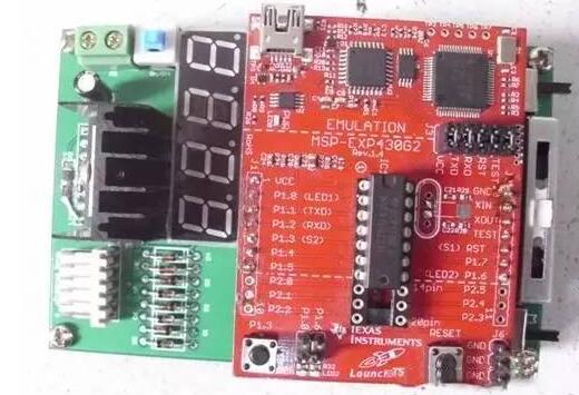
Figure 2.1.1 Physical Map of Launchpad Development Board of MSP430G2 Series
MSP430G2 Series Launchpad Development Board Hardware Resources:
• USB debugging and programming interface can be installed without driver, and has UART serial communication speed up to 9600 baud
• Supports all MSP430G2xx and MSP430F20xx devices in PDIP14 or PDIP20 packages
• Two universal digital I/O pins connected to the green and red LEDs, respectively, provide visual feedback
• Two buttons for user feedback and chip reset
• The device pins can be led through the socket, which can be easily used for debugging and can also be used to add custom expansion boards
• High quality 20-pin DIP socket for easy insertion and removal of target devices
Key device selection and performance index parametersFirst, stepping motor
This work uses the 35BY48BH10 stepper motor manufactured by Changzhou Delilai Electric Appliance Co., Ltd. The technical data, wiring diagram, outline drawing and physical drawing are shown below.
Technical data

2. Wiring Diagram & Outline Drawing & Physical Map

Second, L298N
As a motor-driven core device, the selection of the motor drive chip plays a crucial role in the reliability and performance of the entire system. In this work, the L298N motor driver chip produced by STMicroelectronics ST was selected. The key indicators are as follows:
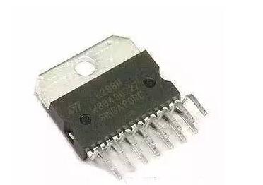
Figure 2.2.1 L298N physical map
1. Supply voltage up to 46V and DC current up to 4A. Fully meet the drive requirements of the stepper motor.
2. Low saturation voltage.
3. Overheat protection.
4. Logic 0 input voltage can reach 1.5V, which can effectively suppress noise; Logic 1 input voltage can be as low as 2.3V, so it can be directly driven by 430 MCU.
In summary, the L298N motor driver chip can fully meet the requirements of this work.
Third, Max7219
Since the IO pin is limited, serial control is used to control the digital tube. The digital tube driver chip selects Max7219. It can drive up to 8 digital tubes and can independently perform refresh scan without the participation of the microcontroller. Each bit is independently controlled and has internal The decoder can choose to decode and not decode. The brightness can be controlled by digital or analog. From all aspects, it is the best choice for this case.
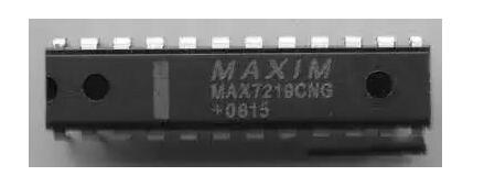
Figure 2.2.1 Physical map of Max7219
The system consists of a single-chip microcomputer, a motor drive circuit, a control circuit, a power supply circuit, and a digital display circuit. The system schematic is shown in Figure 2.3.1.
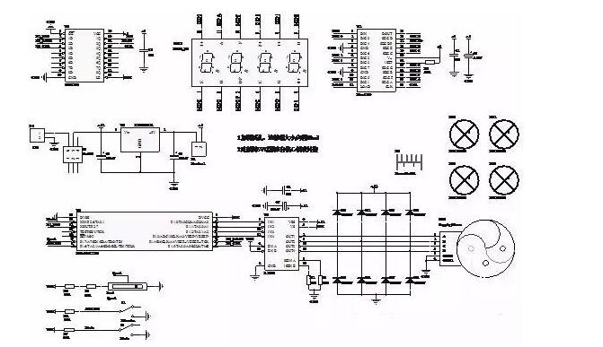
Figure 2.3.1 System Schematic
The following is a detailed introduction of each module:1. Motor drive module
Because L298N logic 1 input voltage can be as low as 2.3V, so can drive directly with 430 one-chip computers, IN1, IN2, IN3 and IN4 receive the foot of the one-chip computer. Vss is connected to the supply voltage, and Vs is connected to the input logic voltage, which can be connected to 3.3V. In this example, to facilitate the wiring, 5V is directly connected.
EN A and EN B are connected with high level, I SEN A, I SEN B are grounded with a small resistance, the purpose is to limit the load current is too large, OUT1, OUT2, OUT3 and OUT4 are directly connected to the stepper motor, because of the inductive component of the motor, The current cannot be mutated, so connect 8 diodes to protect the power supply. In addition, a 100uF capacitor must be connected near Vss and Vs. When this large capacitor is too far away from the device, a small capacitor must be connected nearby.

2. Motor Control Module
As shown in the figure, slippage is used to control the speed of the motor. Speed ​​is connected to pin A7 of the microcontroller. By measuring the voltage value, the appropriate delay time is calculated to achieve the purpose of controlling the speed.
The direction of rotation and Mode are used to change the direction and mode of the motor, ie to select the four-phase four- or four-phase eight-shot mode.
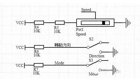
Figure 2.3.3 Motor Drive Module
3. Digital tube display module
Since the IO pin is limited, serial control is used to control the digital tube. The digital tube driver chip selects Max7219. It can drive up to 8 digital tubes and can independently perform refresh scan without the participation of the microcontroller. Each bit is independently controlled and has internal The decoder can choose to decode and not decode. The brightness can be controlled by digital or analog. From all aspects, it is the best choice for this case.
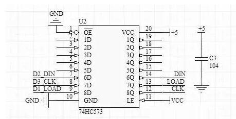
Figure 2.3.4 Level Conversion Module
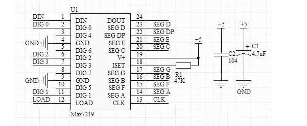
Figure 2.3.5 Digital Tube Drive Module
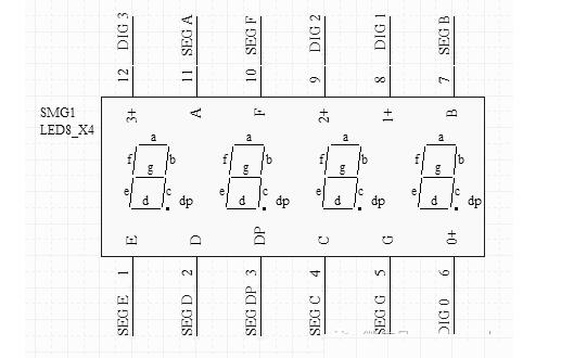
Figure 2.3.6 digital tube
Note that a large capacitor, such as 4.7uF, must be placed near the chip during use.
Since it is a 5V logic level and the MSP430 is a 3.3V level, the level shift is done with the 74HC573.
The digital tube uses a common cathode four-digit tube, which is determined by the driver chip Max7219.
PCB board and system components listPCB board
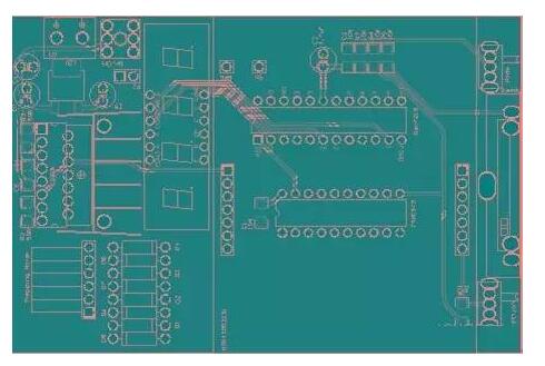
Figure 2.4.1 Front of PCB
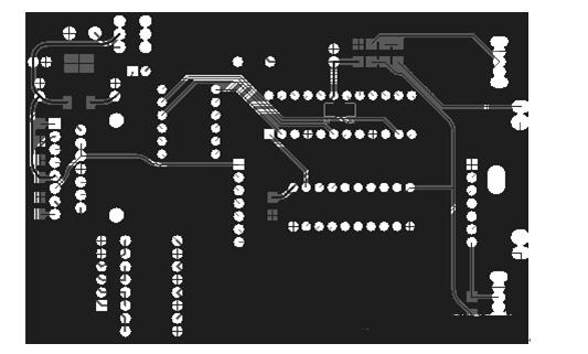
Figure 2.4.2 The back of the PCB
2, the list of system components such as the table
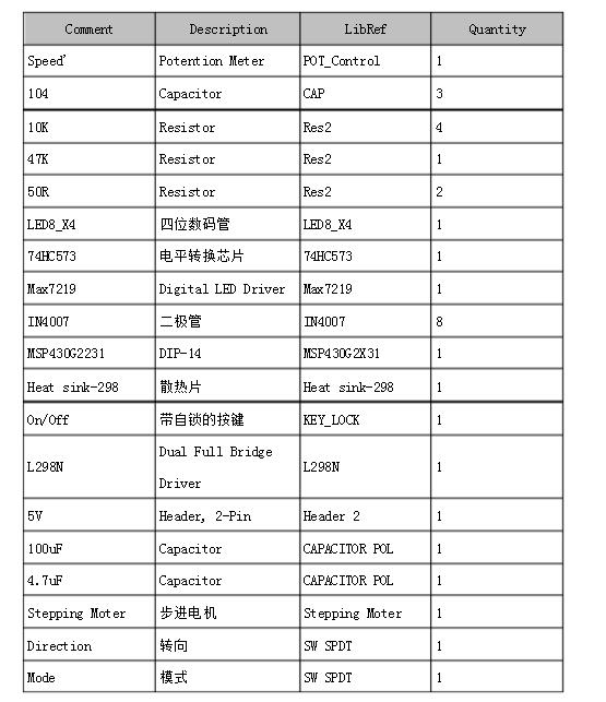
Since it is a high-power device, the 100uF capacitor must be kept as close as possible to the chip. Otherwise, a small capacitor should be added near L298N, and the diode must be kept as close as possible to the output pin of the chip. The capacitance of the Max7219 should also be as close as possible to the chip.
Installation and debugging precautions
Because it is a high-power device, so we must add heat sink, install the first heat sink, then insert L298N, with screws fixed to the heat sink, then welding L298N each pin. The installed experiment board, the experiment board after inserting the landing board, and the experiment board connected to the stepping motor are shown in the figure below.
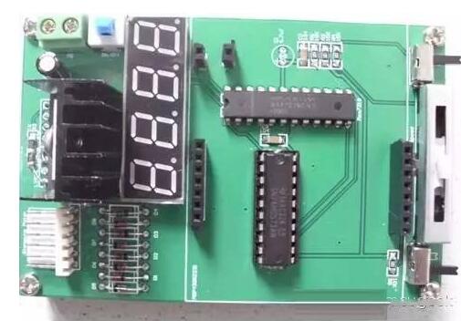
Figure VI.1 Installed Board
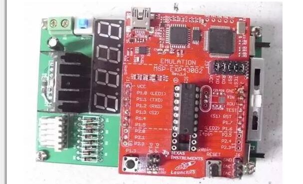
Figure 6.2 Experiment board after inserting the core board of the Launchpad
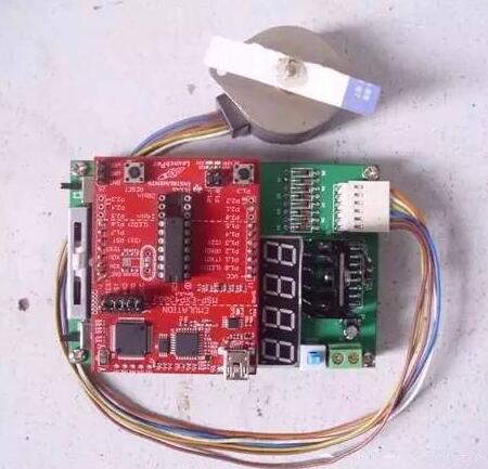
Figure 6.3 Experiment board connected to stepper motor
Procedure flow chart introductionThe software program of this project uses the single-chip microcomputer P1.0, P1.1, P1.2 and P1.3 to output high or low in sequence to generate a certain phase sequence to drive the motor drive chip to drive the stepper motor; the steering and mode are repeated through Scan the corresponding button to determine the appropriate level to control the motor's steering and mode. The system flow chart is shown in Figure 3.1.1.
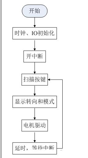
Figure 3.1.1 System Flow Chart
The speed of the rotation is determined by AD's sampling of the sliding voltage. This part is performed in the AD interrupt. The AD interrupt service routine is shown in Figure 3.1.2.
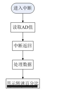
Figure 3.1.2 Interrupt Service Routines
This work is based on the MSP430G2 series Launchpad development platform as the core board, plus the function module backplane, to achieve the four-phase four-shot and four-phase eight beat control of the stepper motor, and to achieve the control of the rotation direction and rotation speed, and use The digital tube shows the percentage of rotation and rotation speed
China Phase Control Stud Thyristor,Stud Version Phase Control Thyristor supplier & manufacturer, offer low price, high quality Dc Power Encapsulation Thyristors,High Power Drives Thyristor Power Control, etc.
The output voltage of thyristor phase-controlled rectifier circuit can be regulated in a large range and has a small fluctuation, which has an impact on the electrical performance of ac power and devices.
Phase Control Stud Thyristor,Stud Version Phase Control Thyristor,Dc Power Encapsulation Thyristors,High Power Drives Thyristor Power Control
YANGZHOU POSITIONING TECH CO., LTD. , https://www.cnchipmicro.com