0 Preface
With the increase in the types of electric vehicles used in modern automobiles and the increase in power levels, more and more types of power supplies are required, including AC power and DC power. These power supplies need to use a switching converter to boost the +12VDC or +24VDC DC voltage provided by the battery to +220VDC or +240VDC through the DC-DC converter, and then convert the DC-AC converter to a commercial frequency AC power supply through the DC-AC converter. Frequency conversion voltage supply. For the pre-stage DC-DC converter, the high-frequency DC-AC inverter part, the high-frequency transformer and the AC-DC rectification part are included, and different combinations are adapted to different output power levels, and the conversion performance is also different. Push-pull inverter circuit has been widely used due to its simple structure and high utilization of transformer core, especially in low- and high-current input medium and small power applications. At the same time, full-bridge rectifier circuit also has high voltage utilization and support output power. High-level features, therefore, this paper uses a push-pull inverter-high-frequency transformer-full-bridge rectification scheme to design a DC-DC converter with 24VDC input-220VDC output and rated output power of 600W, and adopts the AP method to design the corresponding push-pull transformer.
1 How push-pull inverter works
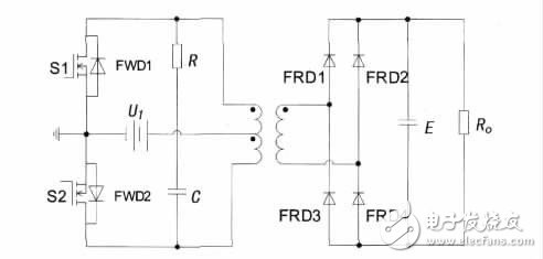
Figure 1 shows the basic circuit topology of a push-pull inverter-high frequency transformer-full bridge rectifier DC-DC converter. By controlling the two switching tubes S1 and S2 to be alternately turned on at the same switching frequency, and the duty ratio d of each switching tube is less than 50%, a certain dead time is left to avoid simultaneous conduction of S1 and S2. The front-stage push-pull inverter inverts the input DC low voltage into an AC high-frequency low voltage, sends it to the primary side of the high-frequency transformer, and couples it through the transformer to obtain the AC high-frequency high voltage on the secondary side, and then passes the reverse fast The full bridge is rectified and filtered by the recovery diode FRD to obtain the desired DC high voltage. Since the back pressure that the switch can withstand is at least twice the input voltage, that is, 2UI, and the current is the rated current, the push-pull circuit is generally used in low- and medium-power applications where the input voltage is low.

Fig.1 Basic circuit topology of push-pull inverter-high frequency transformer-full bridge rectifier DC-DC converter
When S1 is turned on, its drain-source voltage uDS1 is only the turn-on voltage drop of a switching transistor. In the ideal case, uDS1=0 can be assumed, and at this time, an induced voltage is generated in the winding, and according to the same name of the primary winding of the transformer. In the end relationship, the induced voltage is also superimposed on the off S2, so that the voltage that S2 receives when turned off is the sum of the input voltage and the induced voltage is about 2 UI. In practice, the leakage inductance of the transformer will be large. The spike voltage is applied across S2, causing large turn-off losses. The efficiency of the converter is not very high due to the leakage inductance of the transformer. An RC snubber circuit, also called an snubber circuit, is connected between the drains of S1 and S2 to suppress the generation of spike voltage. And in order to provide feedback loop for energy feedback, the freewheeling diode FWD is anti-parallel on both ends of S1 and S2.
2 main circuit of push-pull transformer design
Figure 2 shows the simplified main circuit. Input 24V DC voltage, after large capacitance filtering, connected to the middle tap of the primary side of the push-pull transformer. The other two taps on the primary side of the transformer are connected to two fully-controlled switching device IGBTs, and an RC snubber circuit is added between them to form a push-pull inverter circuit. The output of the push-pull transformer is rectified by full bridge, and the large capacitor is filtered to obtain 220V DC voltage. And the feedback voltage signal UOUT is obtained through the voltage dividing branch.

Figure 2 The main circuit diagram after the simplified push-pull transformer
The CA3524 chip is used as the core to form a control circuit. The switching frequency of the fully-controlled switching device is adjusted by adjusting the resistance and capacitance values ​​between the 6 and 7 pins. The 12 and 13 pins output PWM pulse signals, and alternately control two fully-controlled switching devices through the driving circuit. The voltage feedback signal is input to the 1 pin of the chip. The reference voltage of the voltage feedback signal is input to the 2 pin by adjusting the potentiometer P2, and the PI regulator is combined with the 9 pin COM terminal together with the CA3524 internal operational amplifier to adjust the PWM pulse duty. Than to achieve the purpose of stabilizing the output voltage of 220V.
Specification:
Product Mode:Vidge Max
Puffs:2000Puffs
Oil Capacity: 5.0ml E-Liquid
Battery: 950mAh
Flavor Numbers: 10
Packing Size: 10pcs/box
Salt Nic: 6%
Advantages
Get fully best services from one order to next order.
Support OEM you own Logo.
24 hours online service(Working day) with fast reply.
Support replacement if got bad goods.
Multiple payment methods.
Vidge,Good Looking Colorful E-Cigarette,Cartoon Design E-Cigarette,Dazzle Light Glowing E-Cigarette,Rechargeable Disposable Vape
Shenzhen Ousida Technology Co., Ltd , https://www.osdvape.com