[Abstract] DC stabilized power supply is an indispensable part of various electronic products. Its quality is directly related to the quality of the instrument, providing energy for the stable operation of the equipment. Therefore, mastering the installation and debugging methods of the regulated power supply plays a very important role in the regulated power supply. This article mainly introduces the circuit structure, assembly steps and debugging methods of the LM317 regulated power supply.
introductionWith the rapid development of integrated circuit technology, the voltage regulator circuit has also rapidly realized integration and become an important part of analog integrated circuits. At present, the most common application in the small power regulated power supply is the LM317 adjustable DC regulated power supply. It is one of the most widely used power supply integrated circuits. It not only has the simplest form of a fixed three-terminal voltage regulator circuit, but also has The output voltage is adjustable. In addition, it has the advantages of wide voltage regulation range, good voltage regulation performance, low noise and high ripple rejection ratio. The LM317 is a three-terminal adjustable positive voltage regulator with an output voltage range of 1.25V to 37V and a maximum load current of 1.5A. This regulator is very easy to use.
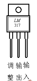
1.LM317 circuit diagram and working principleThe adjustable power supply circuit composed of LM317 is shown in Figure 1. The 220V mains is sent to the LM317 pin 3 (input) through the transformer step-down, diode bridge rectification, capacitor C1 filtering, and the second pin outputs a stable DC voltage. The first pin is the adjustment terminal, and the adjustment terminal and the output terminal are the 1.25V reference voltage. The output voltage is adjusted by two external resistors, that is, the output voltage U0 can be changed by adjusting the resistance of RW. The output voltage is calculated as U0=1.25&TImes; (1+RW/R1).

C1: filter left and right, C2: suppress self-oscillation; C3: filter to reduce the ripple voltage of the output voltage (ie, the alternating voltage component in the output voltage); C4: filter to reduce the fluctuation in U0 . D5, D6 is mainly to protect the LM317, to prevent the capacitor C3, C4 from discharging to the inside of the integrated block when the input or output is short-circuited to damage the chip; R2, LED is the working indication circuit.

(1) Installation
1Compared with LM317 adjustable DC stabilized power supply schematic diagram 2 and bill of materials, check whether the components are complete, the quality is qualified, and the unqualified components should be replaced in time;
2 Identify and detect diodes, capacitors, transformers, resistors, potentiometers, LM317 are consistent with the schematic and good or bad.
Aluminum Electrolytic Capacitors/ Ceramic Capacitors
Aluminum Electrolytic Capacitors/ Ceramic Capacitors
Aluminum Electrolytic Capacitors,Electrolytic capacitor,Ceramic Capacitor
YANGZHOU POSITIONING TECH CO., LTD. , https://www.cnchipmicro.com