From the network implementation level network can be divided into Ethernet, Token Ring, FDDI, ATM, they all specify their physical media, network adapters (network cards), data transmission protocols. From the network coverage, it can be divided into local area network, metropolitan area network, and wide area network. But this just means that the coverage of the network has become larger rather than saying that the implementation of the network has changed. Take the current network as an example. Whether it is a local area network, a wide area network, or the entire Internet, it is basically Ethernet.
Network cardA network adapter is a network card, which is a hardware device that is plugged into a computer motherboard (or integrated on a motherboard). In Ethernet, each network card has a globally unique 48-bit identifier, which is what we often call "MAC address" (usually expressed in groups of hexadecimal per byte, for example: 0a:00:27:00:00 :06). When the computer communicates, the network card is responsible for implementing the carrier sense multiple access technology (CSMA/CD) with collision detection. The network card belongs to the physical layer and the data link layer in the OSI reference model. The part above the network layer is implemented by the protocol stack in the operating system, so the TCP/IP protocol stack only contains the network layer (IP) and the transport layer (TCP, UDP).
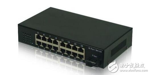
If only two computers communicate, then connect the network cards of the two through a network transmission medium (such as twisted pair), and configure the network layer information (configure the IP address) in the operating system. If three or more computers are communicating, some additional equipment must be used, and a hub is one of them. The hub is also called Hub, which is essentially a multi-port NIC. To understand how it works, build a network topology with GNS3:
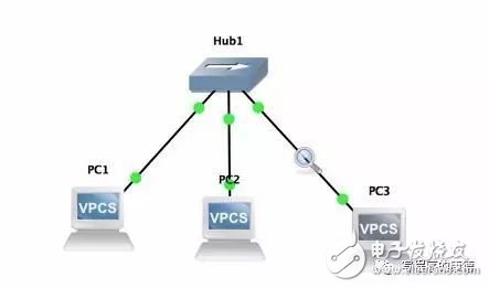
There are three terminals in the above topology. The experiment we are going to do is to receive packets on the Hub1-"PC3 link" when PC1 and PC2 communicate. Configure the IP addresses of PC1, PC2, and PC3 first.

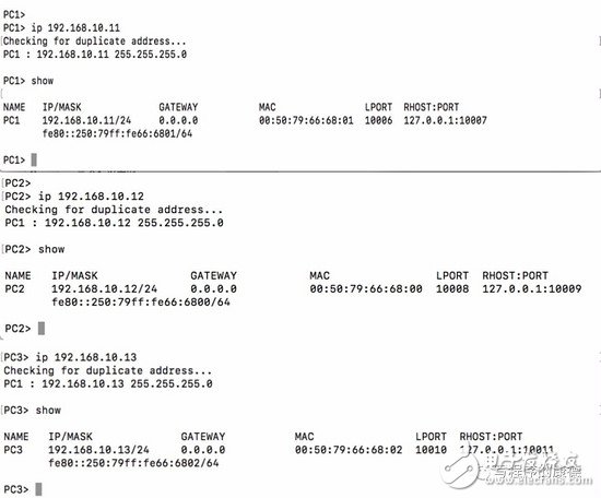
Then open the capture between Hub1 and PC3 and ping PC2 through PC1.

The ping generates a total of two data packets: the ARP packet is a broadcast packet (the destination address is ff: ff: ff: ff: ff: ff: ff). Only the terminal in the broadcast domain can receive it; ICMP is unicast (clear The destination address) packet can only receive packets if it is in a conflicting domain. The machines connected by the hub belong to the same broadcast domain and belong to the same collision domain, so no matter what kind of data packet, every node in the network will receive it (even if the data packet is not related to itself).
The hub and each terminal have a physical link. When PC1 sends data to PC2, it first arrives at the hub, and the hub sends the data out of each of its ports. So even if this communication has nothing to do with PC3, the link between Hub1 and PC3 is still occupied. If PC3 also has a packet to send, then there will be a conflict. (Remember the principle of Ethernet? In shared media There will be "collisions", and this conflict is very "innocent" for PC3 (PC1 and PC2 communication have nothing to do with PC3).
switchSome switches look like hubs, but they are fundamentally different. When the switch forwards data, there is a certain policy. It is based on the mac address table.
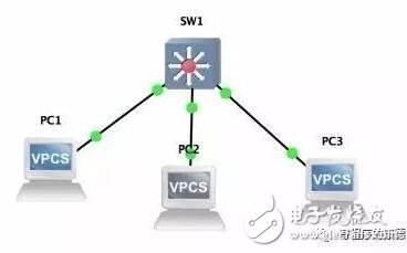
Enable packet capture between SwTIch and PC3, enable packet capture between SwTIch and PC2, and then ping PC2 from PC1 (Wireshark will capture the STP packets on the switch. This is the packet generated by the switch and can be ignored).
SW1 "-" PC3 SW1 "-" PC2
The switch is very "smart", it "knows" that PC1 and PC2 communication does not involve PC3 so only broadcast packets are forwarded to PC3, and subsequent unicast packets are sent directly to the port where PC2 is located. Different from the hub, the collision domain is divided, and a large collision domain is divided into three small collision domains (SwTIch and PC1, SwTIch and PC2, Swtich and PC3 respectively), and each collision domain communication will not affect another. A terminal in a collision domain (data packets between Swtich and PC1 are not received on PC2 and PC3); and the broadcast domain does not change whether the three terminals belong to the same broadcast domain. Reveal the working principle of the switch by describing the communication process between PC1 and PC2:
The PC1 queries the local ARP table to query the corresponding MAC address according to the IP address of the PC2.
If PC1 does not find the MAC address, it sends a broadcast packet.
The broadcast packet reaches the switch, and the switch puts the Mac address and corresponding port of the PC1 into the MAC address table;

If the switch determines that it is a broadcast packet, it initiates a flooding (sent from all ports with the same VLAN as PC1);
Broadcast packets are sent to PC2 and PC3 respectively. PC3 finds that it can directly discard it with itself; PC2 finds that the data packet sent to itself receives the data packet, and further determines that the ARP packet returns an ARP reply. The ARP reply of PC2 is a unicast data packet, the destination address is the MAC address of PC1, and the source address is the MAC address of PC2.
The ARP reply packet of PC2 reaches the switch, and the switch puts the MAC address of PC2 into the MAC address table;

The switch finds that it is a unicast packet. The destination address is 00:50:79:66:68:01. The corresponding port is E0/1. Then send the data packet from E0/1;
PC1 receives the ARP reply packet of PC2, and writes the MAC address of PC2 to the local ARP table**;
PC1 sends an ICMP packet and queries the MAC address based on the IP address. The MAC address of PC2 is found as "00:50:79:66:68:02". Send a unicast package with the destination address "00:50:79:66:68:02";
The unicast data packet reaches the switch, and the switch judges that "00:50:79:66:68:02" is on the port E0/2, and then sends it out from the E0/2 port;
PC2 receives the ICMP packet and generates an ICMP reply packet to send out.
The ICMP reply packet reaches the switch, and the switch determines that the target address is "00:50:79:66:68:01" (PC1) and sends it out from E0/1;
PC1 receives the ICMP reply packet and displays a message "84 bytes from 192.168.10.12 icmp_seq=1 ttl=64 time=0.649 ms";
Through analysis, we can see that the most important content in the switch is the MAC address table, which is the basis for the switch to forward data packets. With this table switch, you can know which port the packet should go from, instead of sending it out from all ports like the Hub. It is not difficult to see through analysis that the most important content in the switch is the MAC address table, which is the basis for the switch to forward data packets. With this table switch, you can know which port the packet should go from, instead of sending it out from all ports like the Hub. Check the MAC address table of the switch by entering show mac address-table in the CLI interface of the switch.
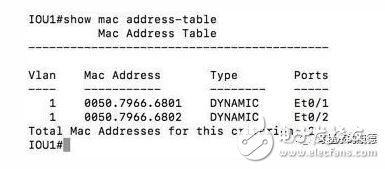
In order to read the speed, the switch will store the MAC address table on a dedicated storage hardware called CAM (Content Addressable Memory). This memory is different from the common memory. Its addressing mode is based on "content" (memory). Is based on address). Therefore, the production process is much more complicated, and the price is much more expensive. The capacity of the general switch configuration is not particularly large. This "weakness" of the switch leads to a "no solution" attack method - the switch does not work properly by sending a large amount of ARP information to the switch to fill the CAM.
Virtual local area networkThe switch divides the collision domain of the Ethernet into multiple collision domains, which improves the utilization of the line, but everyone is still in the same broadcast domain. This network structure is an early network structure, and it has only one broadcast domain. Any other terminal that sends a broadcast packet can be received by other nodes, hence the name of a flat network. This kind of network structure will cause the following problems: 1. Security problem, everyone in the same broadcast domain, any virus in the same person will affect everyone; even more terrible is that if someone illegally accesses the network, it can easily monitor the network. All the data packets; 2. Bandwidth utilization problem, anyone in the network may consume a lot of bandwidth, others may be affected - even unable to use the network normally; 3. Broadcast storm, Imagine a hundred terminals Into the network, various broadcast data packets (ARP, DHCP, etc.) will be flooded throughout the network; splitting a large LAN (broadcast domain) into multiple small LANs is not only safe, easy to manage, but also balanced resource utilization Improve line utilization. So how to split it? The partitioning method is still embodied on the switch. We set a digital ID for each switch port. The ports with the same digital ID belong to the same broadcast domain. For example, in the following figure, switches E0/1, E0/2, E0/4, and E0/7 have the same identifier 100; E0/3 and E0/6 have the same identifier 300 (the following figure is a schematic diagram of the switch)
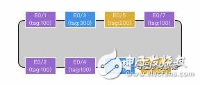
This technology is called a virtual local area network (VLAN). A VLAN represents a broadcast domain (BD). Each switch port can be configured with a VLAN ID to identify the broadcast domain. The switch is in the same VLAN. The broadcast packet in the ID is called flooding.
View all VLANs of the local switch by calling show vlan on the CLI interface of the switch (or broadcast domain, BD, and network in OpenStack and other systems).
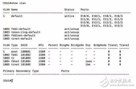
The first column of VLANs represents the VLAN ID, which is a number, name is a memo name, and ports indicate which ports currently belong to this VLAN.
Let's do a test, put PC1 and PC2 in VLAN 100, and put PC3 in VLAN 200.
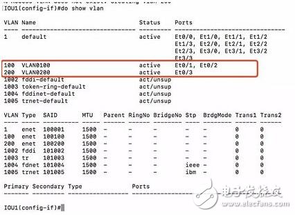
At this time, it is normal to ping PC2 through PC1, and PC1 ping PC3 fails.

By capturing packets between SW1 "-" PC3, we found that ARP packets did not arrive at this link at all, indicating that SW1 has identified that they belong to different VLANs (broadcast domain) so it does not forward packets to this chain. On the road.
In order to prove that the switch forwarding is only related to the MAC address, we change the IP address of PC3 to 192.168.10.10.

It is found that PC1 "-" PC2 can still communicate normally, which proves that the switch only looks at the MAC address of the data packet and completely ignores the IP address.
So how do you implement communication between different VLANs? This requires another network device - the router. This is a very complicated topic, it can be said that it is the basis for building the Internet, so we need to spend a separate chapter to explain.
Anyang Kayo Amorphous Technology Co.,Ltd is located on the ancient city-Anyang. It was founded in 2011 that specializes in producing the magnetic ring of amorphous nanocrystalline and pays attention to scientific research highly,matches manufacture correspondingly and sets the design,development,production and sale in a body.Our major product is the magnetic ring of amorphous nanocrystalline and current transformer which is applied to the communication, home appliances, electric power, automobile and new energy extensively. We are highly praised by our customers for our good quality,high efficiency,excellent scheme,low cost and perfect sale service.
Nano-crystalline Common Mode Choke Cores have high saturation magnetic induction that can reduce the volume of CMC,outstanding ability to resist unblanced current, excellent impedance and tamperature stability.So it can be used to the inverter circuit ,frequency converter.UPS, switching power,EMC filter and new energy.
Nano Cmc Iron Core,Best Cmc Core,New Energy Cmc Core,Utility Cmc Core,Real Cmc Core
Anyang Kayo Amorphous Technology Co.,Ltd. , https://www.kayoamotech.com