MulTIsim is an upgraded version of the electronic circuit simulation software EWB (Electronics Workbench) launched by InteracTIve Image Technologies of Canada in recent years. MulTIsim provides users with an integrated and integrated design lab environment. With MulTIsim, building circuits, simulation analysis, and result output can all be done in one integrated menu. The simulation method is practical, and the components and instruments are very close to the actual situation. The Multisim component library is available in thousands of circuit components and is fully compatible with the components of the more popular circuit analysis software PSpice. Multisim provides a wide range of analysis capabilities including circuit transient analysis, steady state analysis, time domain analysis, frequency domain analysis, noise analysis, distortion analysis and discrete Fourier analysis. In this paper, Multisim is used as the working platform; the second-order low-pass filter circuit is deeply analyzed. Multisim can be used to seamlessly transfer data from schematics to PCB layout kits (such as the Electronics Workbench's Ultiboard) with intuitive interface and easy operation.
2 circuit design
Since the amplitude-frequency characteristic degradation rate of the first-order low-pass filter is only -20 dB/10 f, the difference from the ideal case is too large, and the filtering effect is not good. In order to speed up the rate of descent, bring it closer to the ideal state, and improve the filtering effect, we often use a second-order RC active filter. The improvement measures taken are to add another RC network to the first-order.
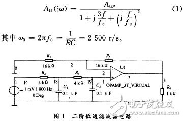
The circuit structure is shown in Figure 1. The upper part of this circuit is a similar amplifier circuit, composed of two resistors R1, Rf and an ideal operational amplifier. Both R1 and Rf are 16 kΩ. The lower half is a second-order RC filter circuit consisting of two resistors R2, R3 and two capacitors C1, C2. Where R2 and R3 are both 4 kΩ, and both C1 and C2 are 0.1 μF. The circuit provides an input signal from an AC voltage source with an adjustable amplitude of 1 mV and a resistor of 1 kΩ.
3 theoretical analysis
3.1 Frequency characteristics
The frequency characteristics of the second-order low-pass filter circuit are:

3.2 passband voltage amplification AUP
At low frequencies, the two capacitors are equivalent to an open circuit. This circuit is the same comparator.
![]()
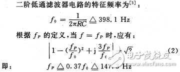
3.3 Characteristic frequency f0 and passband cutoff frequency fP

4 Multisim analysis
4.1 Virtual oscilloscope analysis
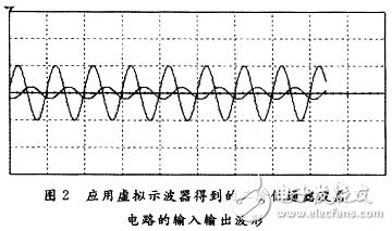
Select the virtual dual-track oscilloscope in the virtual instrument bar of Multisim software, connect the A and B terminals of the oscilloscope to the input and output terminals of the circuit (ie, nodes 1 and 3 in Figure 1), and then click the simulation button to simulate. The following waveform is obtained.
Figure 2 shows the input and output of a second-order low-pass filter circuit with an input signal frequency of 1 kHz and an amplitude of 1 mV. In the figure, the abscissa is time and the ordinate is voltage amplitude. We chose the oscilloscope to scan at 1 ms/div. The vertical axis represents 1 mV per cell and the output mode is Y/T mode. The large amplitude is the input signal, and the small amplitude is the output signal.

Obviously, the frequency of the output signal is consistent with the input signal, indicating that the second-order low-pass filter circuit does not change the signal frequency. It can also be seen from Figure 2 that the amplitude of the output signal is significantly smaller than the amplitude of the input signal when the input signal frequency is large (eg 1 kHz). The theoretical calculation result in the low frequency case is AUP=2; that is, the amplitude of the output signal should be twice the input signal at low frequencies. Obviously, the amplification of the circuit is not ideal when the input signal frequency is large.
Adjust the input frequency to 800 Hz, 600 Hz, 400 Hz, 300 Hz, 200 Hz, 150 Hz, 1 Hz. The output voltage Uo1=2 mV when the input frequency is 1 Hz is obtained by the virtual oscilloscope, that is, AUP=2, which is consistent with the theoretical calculation value. Uo2 = 1.5 mV at an input frequency of 150 Hz. At this time, the output voltage of Uo2 closest to the cutoff is UP=0.707Uo1=1.414 mV. This shows that the cutoff frequency fP is close to 150 Hz.
We found that it is difficult to obtain the exact value of fP only by virtual oscilloscope analysis, nor can we visually understand the influence of the frequency of the input signal on the amplification performance of the circuit. Therefore, the AC analysis in Multisim is used to accurately observe the input and output characteristics of the circuit.
4.2 AC Analysis
Stop Multisim simulation analysis (Multisim simulation analysis and AC analysis cannot be performed simultaneously), select AC Analysis in Analysis from the simulation item in the main menu bar. The parameters are set as follows: the starting frequency is 1 Hz, the ending frequency is 10 MHz, the scanning mode uses decimal, the ordinate is in dB, the output node is selected in Output variables (ie, node 3 in Figure 1), and then click simulate to simulate Analysis, the amplitude-frequency characteristic curve of the circuit is shown in Figure 3.

4.2.1 Measurement of passband voltage amplification AUP
It can be seen from the characteristic curve that the frequency change has little effect on the AUP in the low frequency state, and the AUP decreases sharply as the frequency increases. The output voltage is close to zero at high frequencies. From the dialog box, the maximum ordinate is 6.020 4 dB, which is AUP=2, which is consistent with the theoretical calculation.
4.2.2 Measurement of passband cutoff frequency fP
fP is the frequency corresponding to the ordinate decreasing by 3 dB from the maximum value (6.020 4 dB), that is, the frequency corresponding to the ordinate of 3.020 4 dB. Move the right scale in Figure 3 to near 3.020 4 dB, select it for partial amplification; then move the scale to the ordinate of 3.020 4 dB, and the resulting abscissa is 148.495 2 Hz, ie fP=148.495 2 Hz . This is basically consistent with the theoretical calculations.
4.3 Parameter sweep analysis (parameter sweep)
When the parameters of a component change, the parameter scan analysis function in Multisim can be used to obtain the change of the input and output characteristics of the circuit.
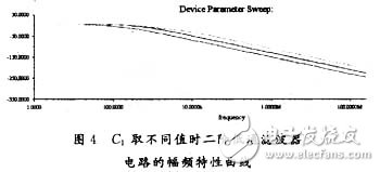
Select parameter sweep in Analysis from the simulation item in the main menu bar. The parameter settings are as follows (to analyze C1 as an example): Select the capacitor device in the device item, select the component name C1, select the capacitance, and use three values ​​of le-006F, le-007F, and le-008F. Click the more option, select AC Analysis, and select node 3 as the output node. Click simulation to simulate, and get the amplitude-frequency characteristic curve of the circuit when C1 takes the above three different values ​​(as shown in Figure 4).

In Figure 4, the corresponding capacitances of the three curves from bottom to top are respectively le-006F, le-007F, and le-008F, and the corresponding cutoff frequencies are 35.550 Hz, 148.493 7 Hz, and 193.375 6 Hz, respectively. It is clear that the decrease in C1 causes the cutoff frequency of the circuit to increase and the pass band to become wider. The change in C1 has almost no effect on the voltage gain.
Using a similar method, we get the effect of C2, R1, R2, R3 and Rf on the circuit performance as follows: C2, R2 and R3 become smaller, which will cause the circuit's cutoff frequency to increase and the passband to widen. The changes in C2, R2 and R3 have little effect on the voltage gain. R1 is inversely proportional to the output voltage amplitude, Rf is proportional to the output voltage amplitude, but changes in R1 and Rf do not affect the frequency characteristics of the circuit.
5 Conclusion
From the above analysis, the simulation analysis results in Multisim are very close to the theoretical calculation results. Multisim is both a software for electronic circuit design and simulation, and a very good teaching tool for electronic technology. Multisim is used in classroom teaching and enriches the content of multimedia assisted instruction in electronic technology. It is a leap in the development of educational technology. Multisim greatly enriches the teaching methods of electronic circuits with its development, flexibility, richness, vividness, real-time interaction and high efficiency. It expands the breadth and depth of teaching content and improves electronic technology. Teaching quality provides yet another effective means.
Pharmaceuticals,2-Methyl- Propanoic Acid Monohydrate Price,2-Methyl- Propanoic Acid Monohydrate Free Sample,Pure 2-Methyl- Propanoic Acid Monohydrate
Zhejiang Wild Wind Pharmaceutical Co., Ltd. , https://www.wild-windchem.com